Procedure for sorting flows in a transport network carrying circuit data flows

a technology of circuit data flow and flow sorting, which is applied in the field of circuit data flow sorting process, can solve the problems of inability to practice, flow untidy and irregular, and is more difficult to use in the future,

Active Publication Date: 2005-06-30
TELECOM ITALIA SPA
View PDF4 Cites 3 Cited by
  • Summary
  • Abstract
  • Description
  • Claims
  • Application Information

AI Technical Summary

Benefits of technology

[0016] In this way, when a sub-network is apparently saturated because there is no space for allocating a new data flow, the procedure described herein may be applied to optimise the band occupied by the current flows and possibly sort the sub-network to create space for the new flows. The result is a procedure for optimising the band employed by the flows configured on the sub-network which preserves the theoretical qualities of an optimal routing algorithm combining the possibility of minimising the number of operations required to reach this condition.

Problems solved by technology

The traffic demand to be carried by the network must be entirely defined beforehand to work these theoretical algorithms, which in practice is impossible.
The biggest problem, on the other hand, to be faced when optimising a sub-network which is already operational in terms of occupied band, is how to change circuit configuration to implement the optimised configuration without disrupting the service, with minimum effects perceived by customers.
Flows are often untidy and irregular in a sub-network that has been working for some time due to flow allocation changes which inevitably occur in the course of time.
These gaps are often employed for smaller flows and even smaller gaps are created, which are even more difficult to use in the future.
This effect in the middle term progressively worsens the ratio between the band effectively occupied by data in the sub-network and the total available band of sub-network, making the configuration of new flows in the sub-network effectively impossible.

Method used


Image

  • Procedure for sorting flows in a transport network carrying circuit data flows
  • Procedure for sorting flows in a transport network carrying circuit data flows
  • Procedure for sorting flows in a transport network carrying circuit data flows

Examples


Embodiment Construction

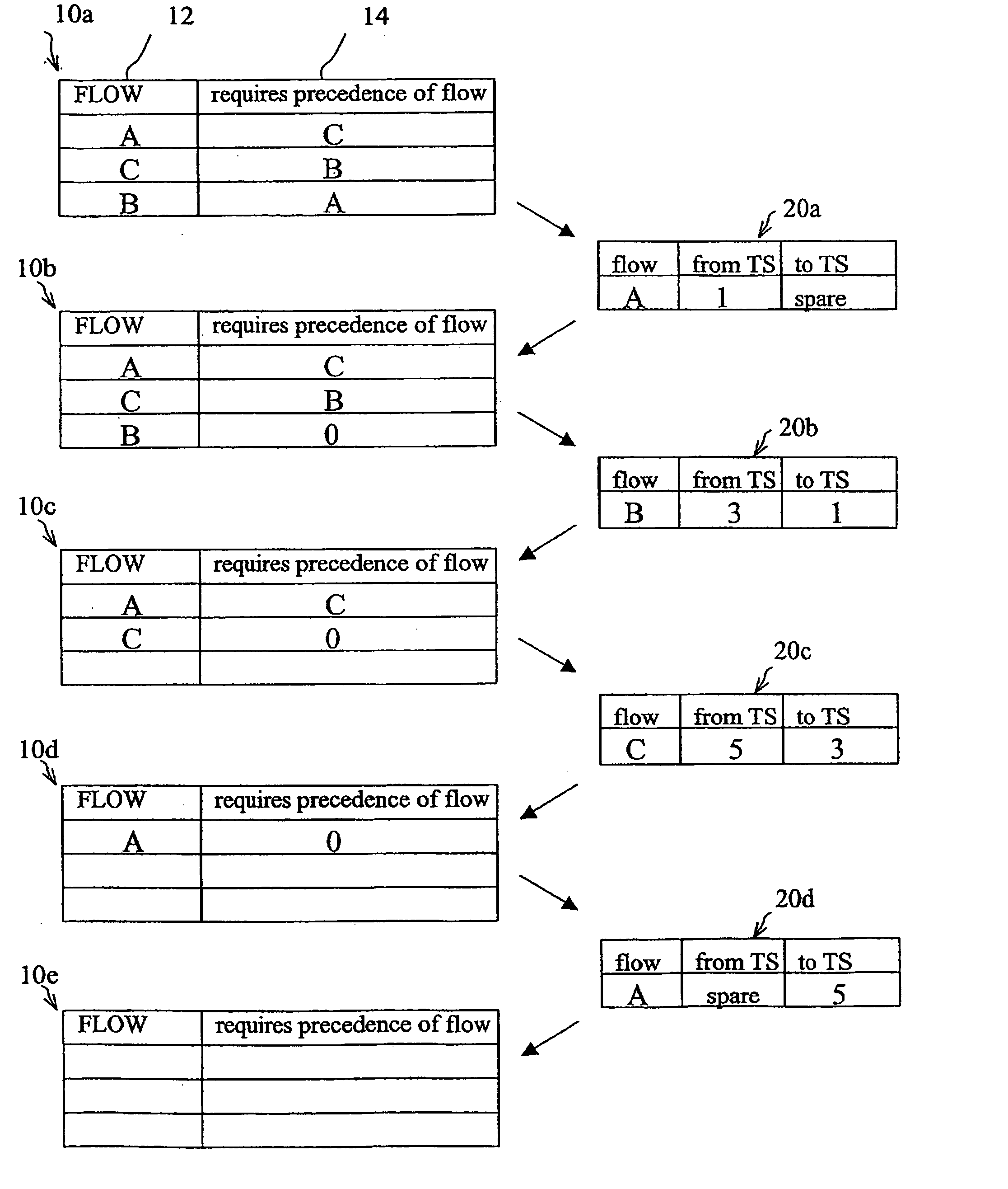
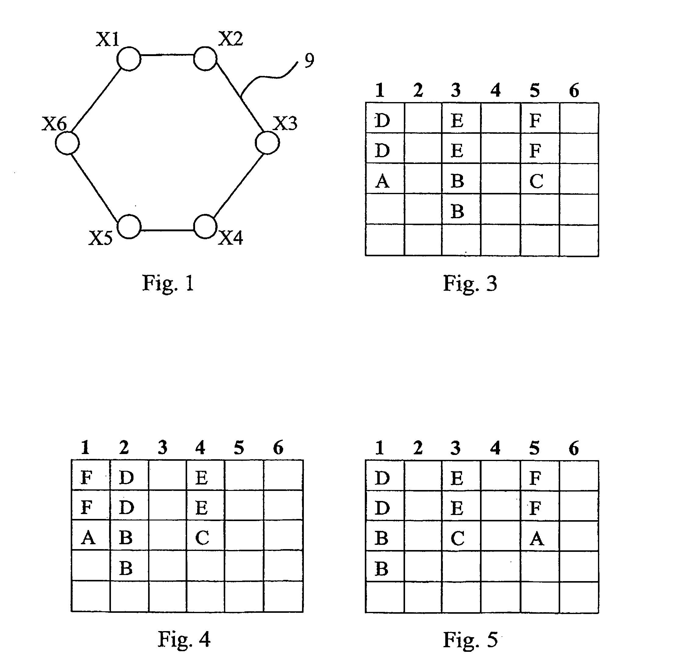
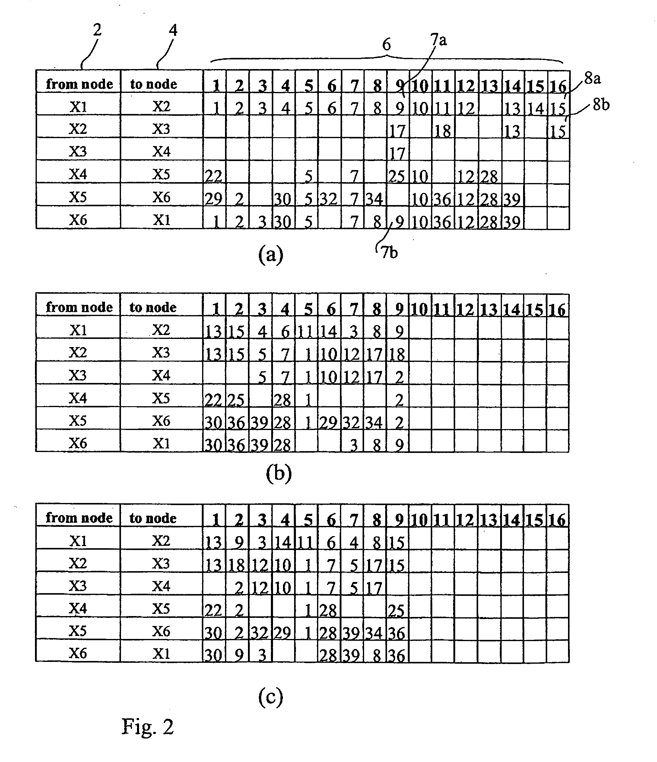
[0024] The following detailed description illustrates a flow sorting procedure in a transport network ring sub-network carrying circuit data flows. The sub-network is schematically shown as a set of slots (which are time, spatial, frequency or wavelength intervals between pairs of linked sites). Specifically, the illustrated procedure can be applied to sorting SDH / SONET (Time Division Multiplexing) type networks and WDM (Frequency Division Multiplexing) type networks. The term “slot” will be used to indicate “time slots” in the case of SDH / SONET networks and “λ-slots” in the case of WDM networks.

[0025] Similarly, the invention can be applied to networks in which data flow multiplexing is obtained through either space division (SDM, Space Division Multiplexing) or frequency division (FDM, Frequency Division Multiplexing), in which case the term “slot” will be associated to space and frequency intervals, respectively.

[0026] The ring sub-network may implement MS-SPRing technology (OM...


PUM


Abstract

A procedure for sorting a plurality of circuit data flows (7, 8, . . . ) located, according to an initial configuration, in a plurality of sets of slots (space, time, frequency or wavelength) in a transport sub-network, comprising the following steps:—calculating a theoretical configuration in which flows are optimised in terms of occupied band by applying a theoretical flow routing algorithm; on the basis of the theoretical configuration defined above, exchanging the position of the flows in the sub-network slots to obtain an optimal arrangement which minimises the occupied slots; flows whose position corresponds to the position assumed by the flows in the initial position are identified to reduce the number of exchanges; defining and implementing a minimum shift sequence of single flows needed to shift each single flow from an initial position occupied in the initial flow configuration to a final position corresponding to the position assumed by the flow in the optimal slot set arrangement.

Description

TECHNICAL FIELD [0001] The invention refers to transport networks carrying circuit data flows, of the synchronous and asynchronous type, employing either space, time, frequency or wavelength multiplexing, and specifically refers to a procedure for sorting circuit data flows in a sub-network. BACKGROUND ART [0002] As known, data are transmitted in TDM (Time Division Multiplexing) transport networks in time windows or sets of slots (called “time slots”) whose length is fixed, each of which contains one or more circuit data flows defined by the implemented protocol. Networks of this kind include, for example, SDH (Synchronous Digital Hierarchy) or SONET (Synchronous Optical Network) networks. The term “slot” therefore means “time interval” in this case. [0003] In WDM (Wavelength Division Multiplexing) networks, data are transmitted on different wavelengths λi, which replace the multiplexing time slots and consequently may be called “λ-slots”. Similarly, SDM (Space Division Multiplexing...

Claims


Application Information

Patent Timeline
Patent Type & Authority Applications(United States)
IPC IPC(8): H04J3/16H04J14/02H04L12/24H04Q11/04
CPCH04J3/1611H04J14/0227H04J14/0283H04J14/0284H04J14/0286H04L41/0896H04J14/0291H04J2203/0067H04J2203/0098H04L41/083H04J14/0287
Inventor ALLASIA, ANDREAGIANCOLA, ANDREAVACCARONE, GIANLUCAFERRARIS, GIUSEPPE
Owner TELECOM ITALIA SPA
Why Eureka
Try Eureka