
Decoding apparatus and decoding method

a decoding apparatus and decoding technology, applied in the field of decoding apparatus and decoding method, can solve the problems of serious decoding failures and inevitable image quality degradation to a great degree, and achieve the effect of eliminating drawbacks

Inactive Publication Date: 2005-06-30
SONY CORP
View PDF2 Cites 22 Cited by
  • Summary
  • Abstract
  • Description
  • Claims
  • Application Information

AI Technical Summary

Benefits of technology

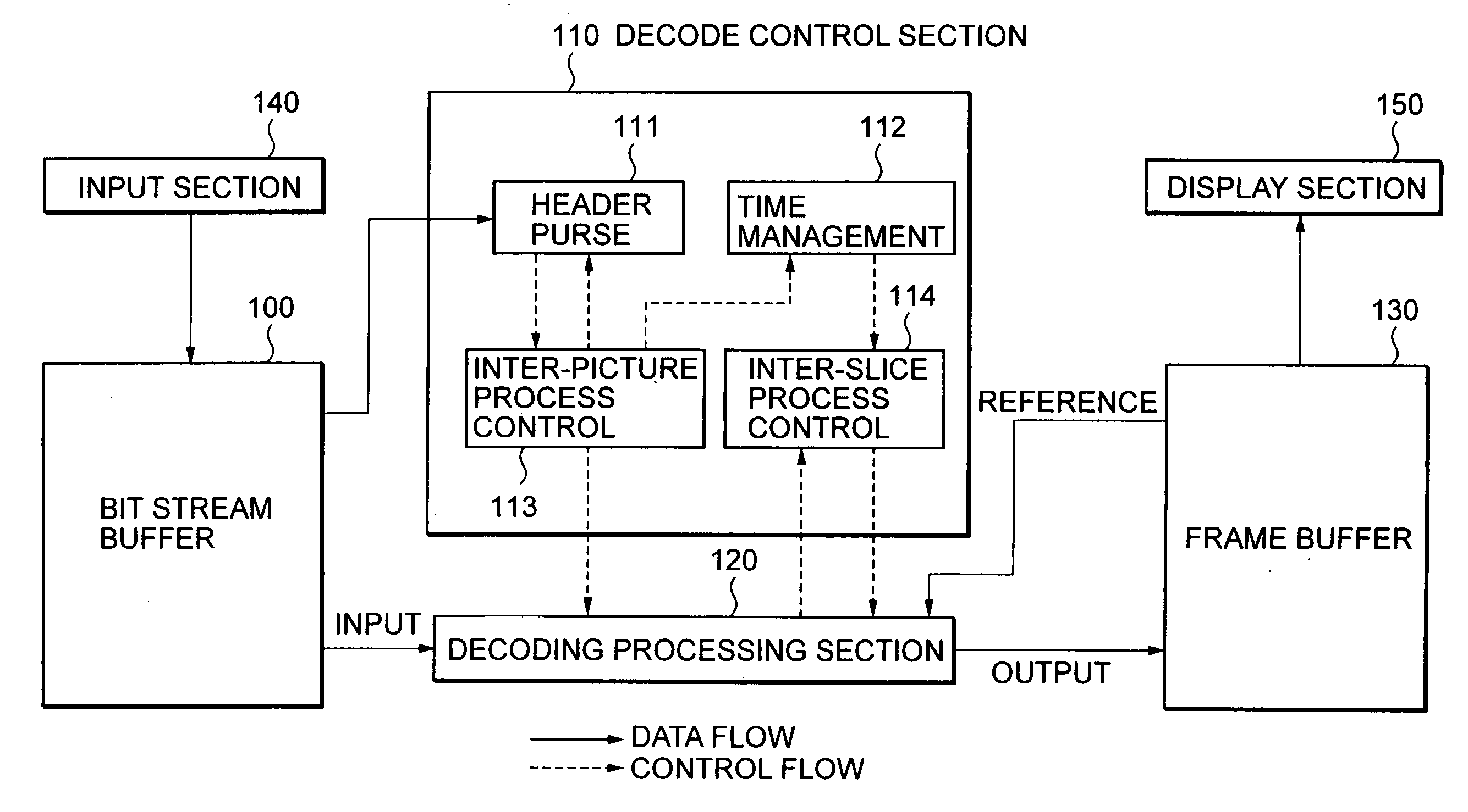
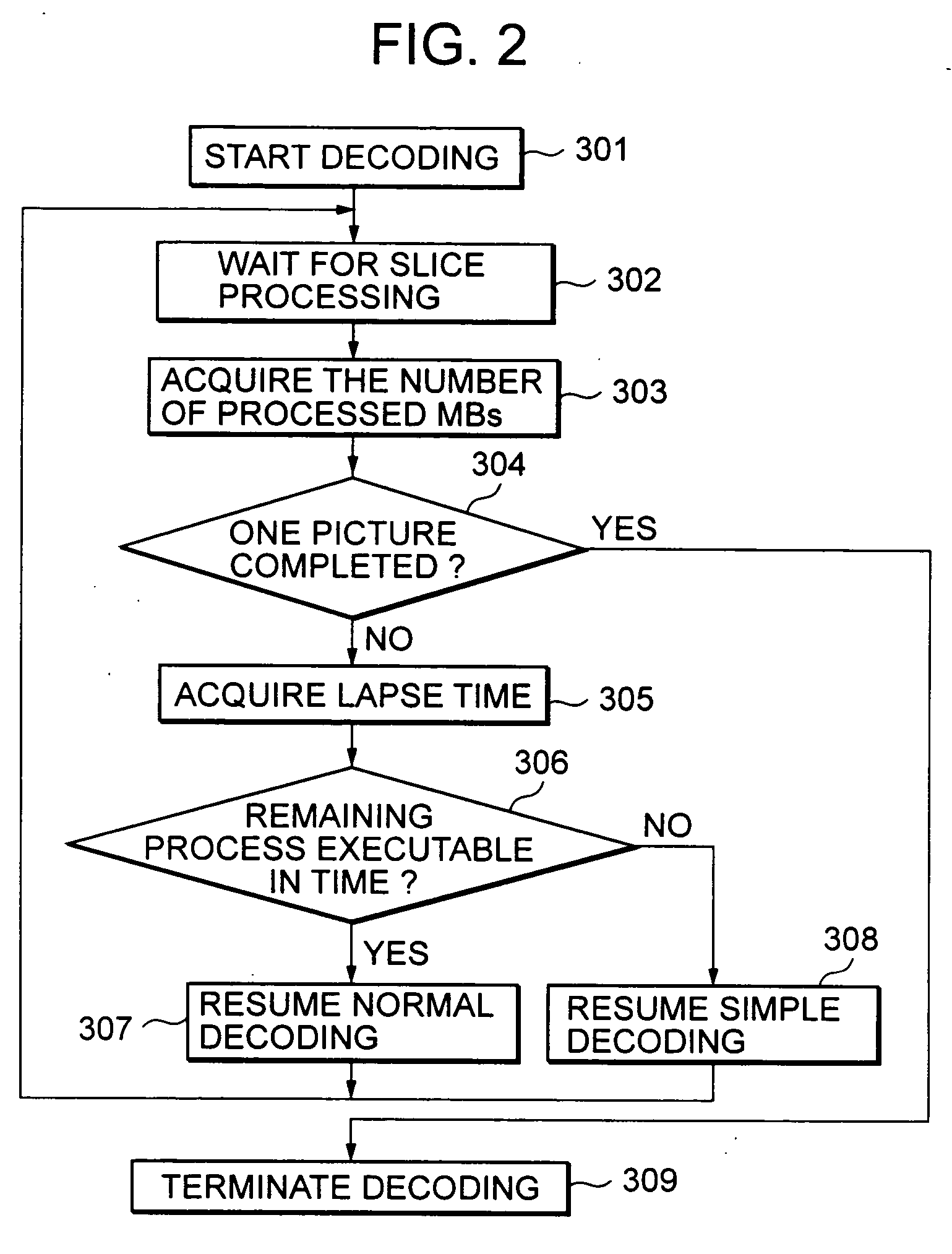
[0082] According to the present invention, therefore, when decoding digitally compressed and encoded pictures and displaying the decoded pictures in real time, the time during a decoding process is measured; a normal decoding function for performing a normal decoding process and a simple decoding function for performing a simple decoding process are provided, the simple decoding process decoding at a higher speed and in a shorter time than the normal decoding process; a decoding operation is performed with temporary stopping during the decoding process; and in accordance with the measured time, the decoding operation is switched to either the normal decoding process or the simple decoding process during the decoding process. Thus, a video decoder compatible with, for example, 4:2:2P@HL can be realized effectively.
[0099] In this manner, the present invention can readily eliminate the drawbacks of a conventional apparatus, the drawbacks being inevitable image quality deterioration to a great degree because the decoding process is terminated when a predetermined time (one frame period) has lapsed, and also serious failures of decoding when this countermeasure is performed for an I picture and a P picture.

Problems solved by technology

The drawbacks to be solved by this application are inevitable image quality deterioration to a great degree because a conventional apparatus terminates the decoding process when a predetermined time (one frame period) has lapsed, and also serious failures of decoding when this countermeasure is performed for an I picture and a P picture.

Method used


Image

  • Decoding apparatus and decoding method
  • Decoding apparatus and decoding method
  • Decoding apparatus and decoding method

Examples


Embodiment Construction

[0120] The decoding apparatus of the present invention is to be used in a system that decodes digitally compressed and encoded pictures and displays the decoded pictures in real time, including a decoding control section having a function for measuring a time during a decoding process; and a decoding processing section for performing a decoding operation with temporary stopping during the decoding process, in cooperation with the decoding control section; wherein the decoding processing section further has a simple decoding function for performing a simple decoding process that decodes at high speed in a short time, in addition to a normal decoding function for performing a normal decoding process; and in accordance with an instruction from the decoding control section, the decoding operation of the decoding processing section is able to be switched to either the normal decoding process or the simple decoding process during the decoding process.

[0121] Further, the decoding apparatu...


PUM


Abstract

A video decoder compatible with 4:2:2P@HL is effectively realized. An inter-picture process control section provides information to a decoding processing section regarding which picture is being used as a reference picture. A decode start is also notified to a time management section. An inter-slice process control section determines whether the decoding process is continuing normally, continuing as a simple decoding process, or stopped. This information is sent from the inter-slice process control section to the inter-picture process control section. The time management section generates a decode start time (frame sync signal) and measures a lapsed time after the decode start. When the decode start time comes, the inter-picture process control section is notified of this. In response to a request from the inter-slice process control section, the lapsed time after the decode start and the remaining time until the next frame sync signal is generated are notified.

Description

CROSS REFERENCE TO RELATED APPLICATIONS [0001] The present application claims priority from Japanese Application No. JP2003-359771, filed in the Japanese Patent Office on Oct. 20, 2003, the disclosure of which is hereby incorporated by reference herein. BACKGROUND OF THE INVENTION [0002] The present invention relates to a decoding apparatus and a decoding method suitable for use with a video decoder compatible with, e.g., 4:2:2P@HL. More specifically, a video decoder can be realized which is capable of a real time operation compatible particularly with 4:2:2P@HL by using a realizable circuit scale. [0003] A conventional video decoder compatible with 4:2:2P@HL shortens the total process time by adopting a slice decoder (for example, refer to Japanese Patent Application Publication No. 2001-359107). However, this technique does not describe directly shortening the process time itself as in the present invention. [0004] MPEG2 (Motion Picture Coding Experts Group / Motion Picture Experts ...

Claims


Application Information

Patent Timeline
Patent Type & Authority Applications(United States)
IPC IPC(8): H04N7/12H04N19/50H04N19/102H04N19/134H04N19/174H04N19/176H04N19/186H04N19/196H04N19/44H04N19/503H04N19/577H04N19/61H04N19/625H04N19/895
CPCH04N19/139H04N19/176H04N19/70H04N19/61H04N19/577H04N19/156H04N19/174H04N19/44H04N19/895H04N19/109
Inventor HATTORI, MASAKAZU
Owner SONY CORP
Learn More