Speaker apparatus

Inactive Publication Date: 2005-06-30
PIONEER CORP +1
View PDF11 Cites 38 Cited by
  • Summary
  • Abstract
  • Description
  • Claims
  • Application Information

AI Technical Summary

Benefits of technology

[0017] A problem important to these in-car audio systems is to reduce a thickness of a speaker apparatus so that the speaker apparatus can be mounted into a space where a diameter of depth is limited such as a door and a ceiling panel of a vehicle.
[0018] However, in a conventional speaker apparatus 1 in which a voice-coil bobbin 11 is elastically supported by a damper 25 as described above, a space in which the damper 25 is disposed must be ensured between a diaphragm 9 and a magnetic circuit 3, so that an installation space for the damper 25 makes it difficult to reduce an axial dimension of the speaker apparatus 1 and becomes a bottleneck for a reduction in the thickness of the speaker apparatus 1.
[0019] In addition, the damper 25 is generally larger in stiffness than an edge 7 and suffers mechanical fatigue due to long term use earlier than the edge 7 does, and there is a risk that degradation in a control perform

Problems solved by technology

A problem important to these in-car audio systems is to reduce a thickness of a speaker apparatus so that the speaker apparatus can be mounted into a space where a diameter of depth is limited such as a door and a ceiling panel of a vehicle.
In add

Method used


Image

  • Speaker apparatus
  • Speaker apparatus
  • Speaker apparatus

Examples


Example

First Embodiment

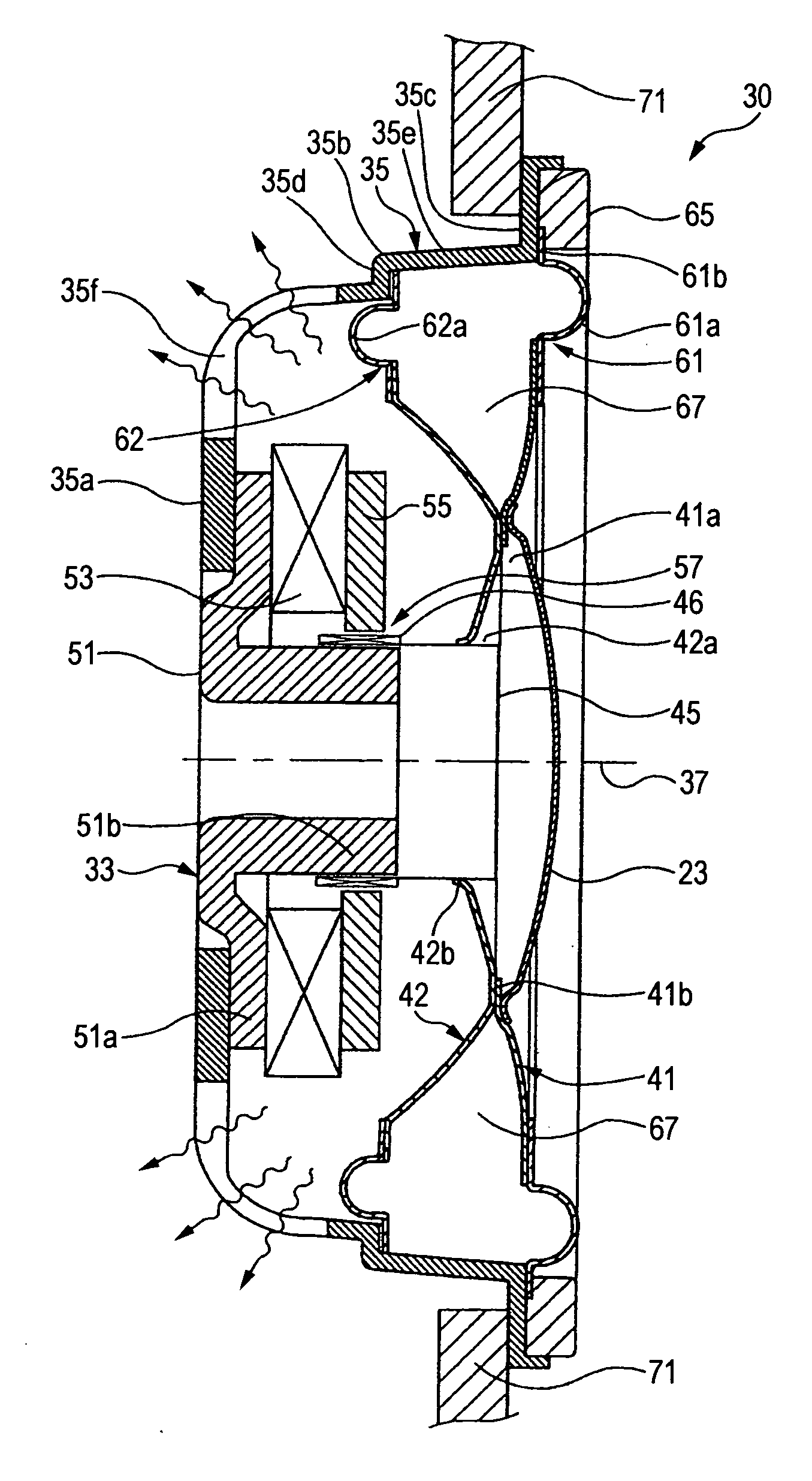
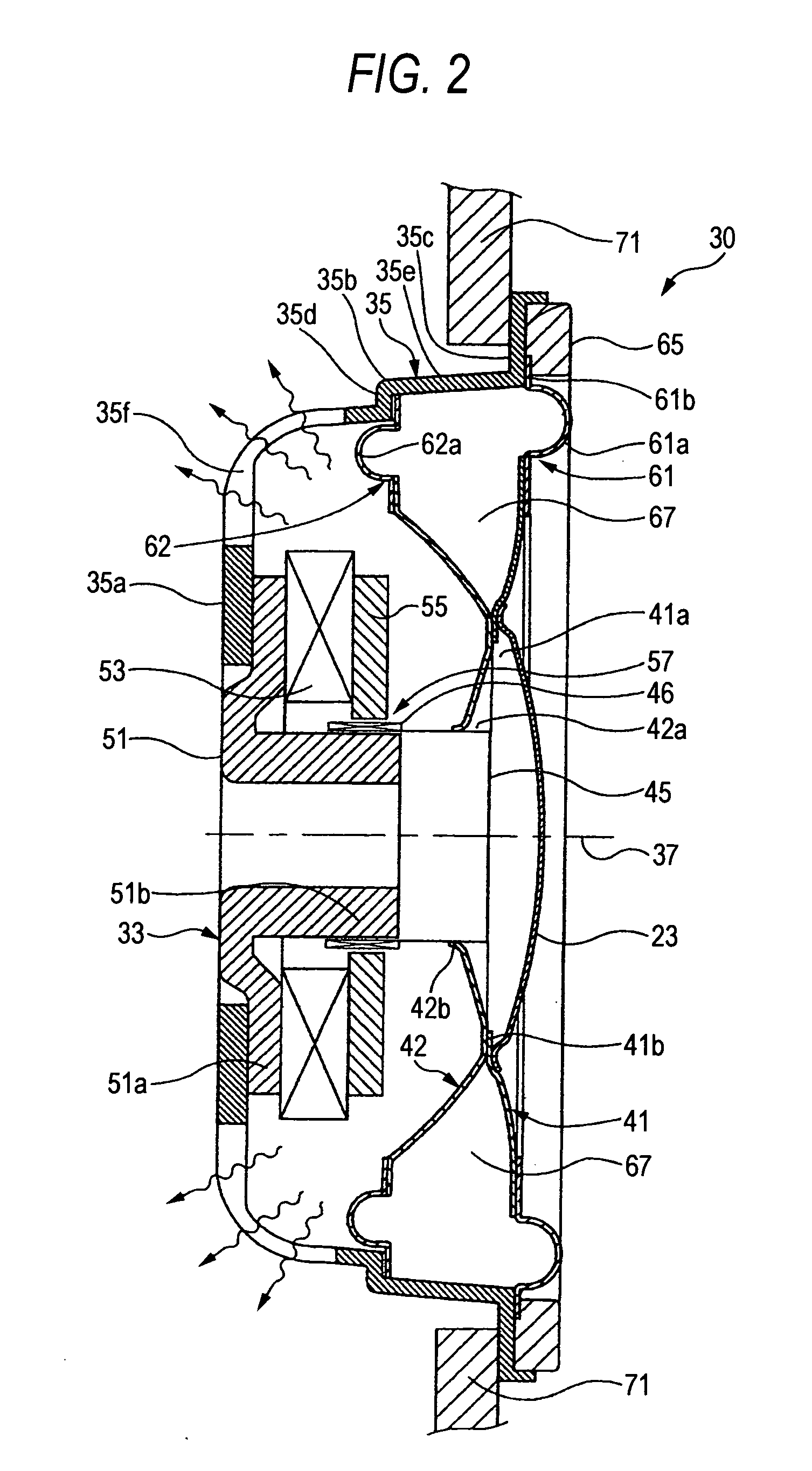
[0029]FIG. 2 is a longitudinal sectional view of a first embodiment of a speaker apparatus according to the invention, and FIG. 3 is an explanatory view of an operation of the speaker apparatus shown in FIG. 2 when being driven.

[0030] As shown in FIG. 2, a speaker apparatus 30 of the first embodiment is configured with a magnetic circuit 33, a frame 35 to which the magnetic circuit 33 is attached on a rear end, a first diaphragm 41 and a second diaphragm 42, which are arranged coaxially with a driving direction (direction parallel to a center line 37 of the speaker apparatus 30), and a voice coil 46 wound on a cylindrical voice-coil bobbin 45.

[0031] The magnetic circuit 33 is configured with a yoke 51 having a structure in which a cylindrical center pole 51b is projected from a center of a disk-shaped plate 51a, a ring-shaped magnet 53 loosely fitted on a periphery of the center pole 51b, and a ring-shaped top plate 55, which is equipped to be loosely fitted on a ...

Example

Second Embodiment

[0056]FIG. 4 is a longitudinal sectional view of an essential portion of a second embodiment of a speaker apparatus according to the invention.

[0057] In a speaker apparatus 40 according to the second embodiment, the first diaphragm 41 and the second diaphragm 42 which are coaxially arranged in the speaker apparatus 30 of the first embodiment shown in FIGS. 2 and 3 are connected by ribs 81 (connecting members) as shown in FIG. 4. The ribs 81 are arbitrarily equipped at a plurality of locations at predetermined intervals.

[0058] Since the first and second diaphragms 41 and 42 are connected by the ribs 81, the rigidity of each of the first diaphragm 41 and the second diaphragm 42 which form the sealed spaced 67 therebetween is strengthened, whereby high-quality sound reproduction can be realized by the improvement of the propagation speed of sound vibration and the like.

[0059] In addition, since the first and second diaphragms 41 and 42 are connected by the ribs 81,...


PUM


Abstract

A speaker apparatus including: a first diaphragm; a second diaphragm arranged coaxial with the first diaphragm along a driving direction; a frame having diaphragm supporting portions; and a voice-coil bobbin, wherein outer circumferential portions of the first diaphragm and the second diaphragm are fixed to the diaphragm supporting portions respectively, inner circumferential portions of the first diaphragm and the second diaphragm are connected together and fixed to the voice-coil bobbin so as to make a sealed space between the first diaphragm, the second diaphragm and the frame, and the voice-coil bobbin is supported by springiness of a gas contained in the sealed space.

Description

CROSS-REFERENCE TO RELATED APPLICATION [0001] The invention claims priority to Japanese Patent Application No. JP 2003-428374 filed on Dec. 24, 2003. The disclosure of the prior application is incorporated herein by reference in its entirety. BACKGROUND OF THE INVENTION [0002] 1. Field of the Invention [0003] The present invention relates to a speaker apparatus, and more particularly, to an improvement for realizing a reduced thickness of a speaker apparatus by reducing a dimension in an axial direction thereof. [0004] 2. Description of the Related Art [0005]FIG. 1 shows a conventional construction of an general type of an electrodynamic speaker apparatus. [0006] This speaker apparatus 1 is configured with a magnetic circuit 3, a frame 5 to which the magnetic circuit 3 is attached on a rear end, a cone-shaped diaphragm 9 having a peripheral roll-shaped edge 7 fixed to a diaphragm supporting portion 5a, which is a front end of the frame 5, and a voice coil 12 wound on a cylindrical v...

Claims


Application Information

Patent Timeline
IPC IPC(8): H04R9/02H04R7/02H04R7/12H04R7/16H04R9/04
CPCH04R7/18H04R2499/13H04R9/042H04R9/041
Inventor KOBAYASHI, HIROYUKIMATSUDA, KYOICHI
Owner PIONEER CORP
Why Eureka
Try Eureka