Refractory metal and alloy refining by laser forming and melting

a technology of refractory metal and alloy, which is applied in the direction of vehicle route interaction devices, railway components, nuclear engineering, etc., can solve the problems of consuming a significant amount of furnace time, and slowing down the overall process. , to achieve the effect of reducing the cycle tim

Active Publication Date: 2005-06-30
MATERION NEWTON INC
View PDF10 Cites 71 Cited by
  • Summary
  • Abstract
  • Description
  • Claims
  • Application Information

AI Technical Summary

Benefits of technology

The technical effect of this patent is to reduce the time it takes to remove and re-use a refractory metal part, such as a sputtering target.

Problems solved by technology

The technical problem addressed in this patent is the need for a more efficient and cost-effective method for producing high purity refractory metal parts, such as tantalum plates for sputtering targets. The current methods are slow and result in a low yield of final product. Additionally, there is a need to rejuvenate the refractory metal to eliminate the need to recycle the whole target after only a minor share of the tantalum plate has been consumed. The invention aims to produce a fully dense deposit with macro- and micro-mechanical properties at least equivalent to traditionally melted, consolidated, rolled and annealed parts, increase yield recovery, decrease fabrication time and costs, decrease recycling cost, and shorten the cycle time between removing the refractory metal part from service and getting it back to service.

Method used


Image

  • Refractory metal and alloy refining by laser forming and melting
  • Refractory metal and alloy refining by laser forming and melting
  • Refractory metal and alloy refining by laser forming and melting

Examples


Embodiment Construction

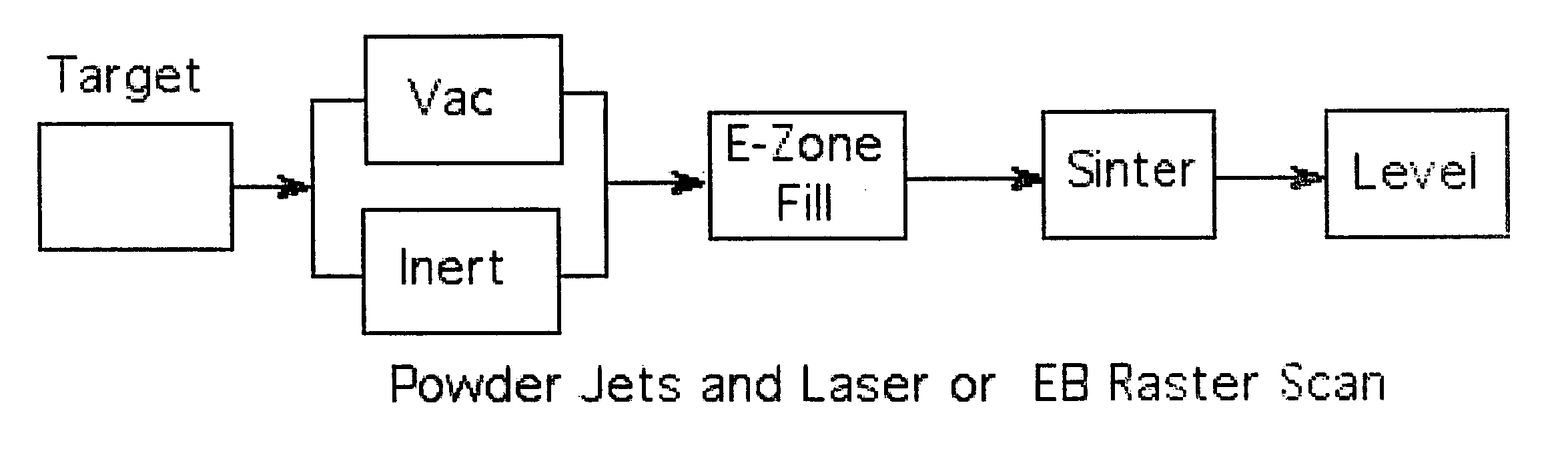
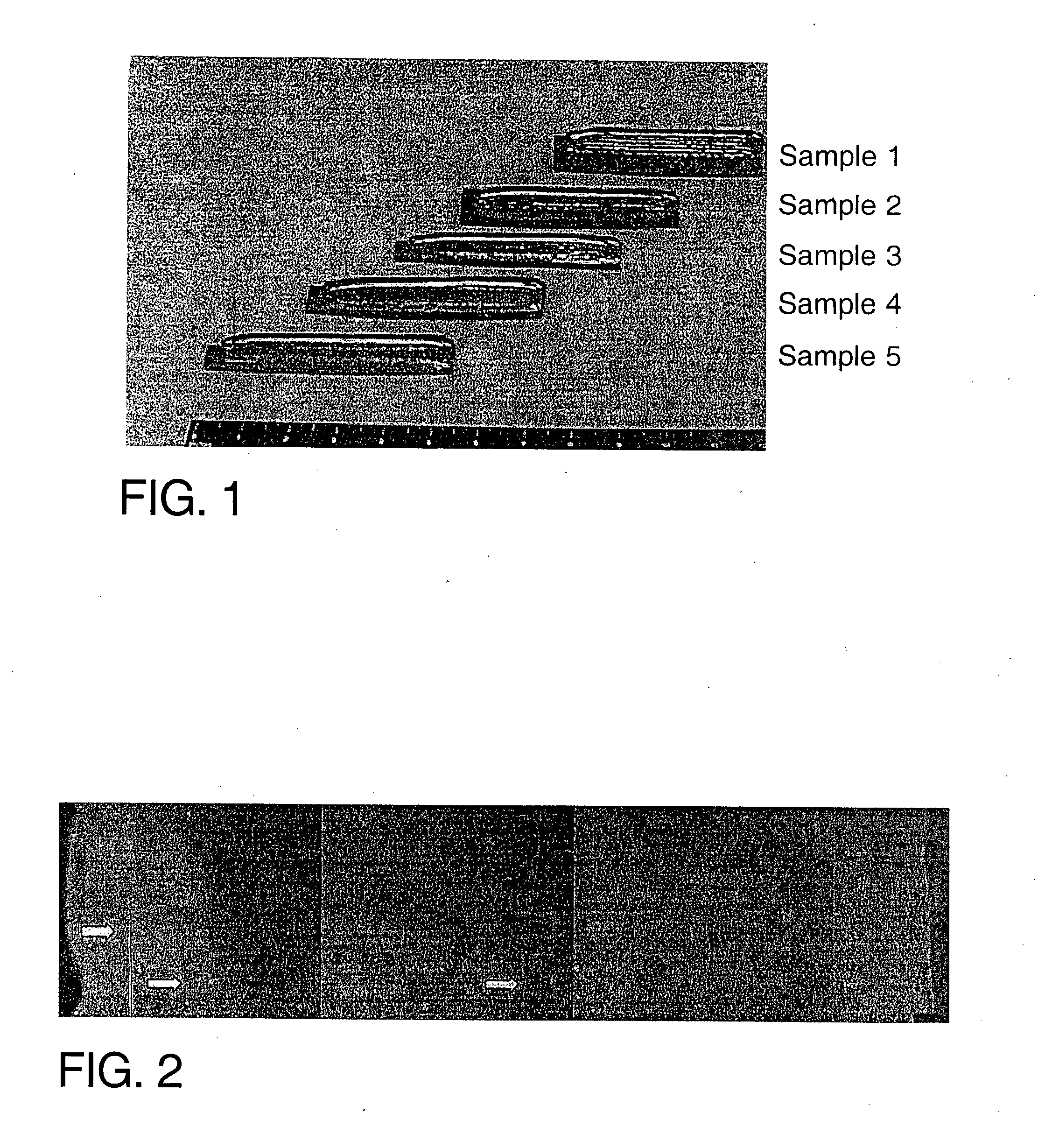
[0029] An embodiment of the present invention is a laser process to produce high purity refractory metal and alloys formed from refractory metal powder. The tantalum powder (−120+325 mesh), and a tantalum plate substrate applied in a depositing apparatus as described in U.S. Pat. No. 6,269,536, incorporated herein by reference in its entirety). The laser energy was approximately 17 kW delivered. FIG. 1 shows the five deposits formed from the laser process. Each deposit is the result of approximately five to seven layers with each layer being approximately 0.010″ thick.

[0030] The physical property differences described above also meant the deposition rates had to be much lower than for titanium. The higher melt temperature and thermal conductivity of tantalum compared to titanium meant the tantalum molten pool was probably smaller and a smaller quantity of powder could be melted by the available laser power.

[0031] Table 1 shows the results of the chemical analysis (GDMS) of the sta...


PUM

PropertyMeasurementUnit
Fractionaaaaaaaaaa
Fractionaaaaaaaaaa
Fractionaaaaaaaaaa

Abstract

A process to chemically refine and consolidate tantalum, niobium and their alloys to a fabricated product of net shape or near-net shape with higher throughput, more consistency, and lower manufacturing costs compared to prior art routes or rejuvenate damaged and deteriorated refractory metal parts. Powder metal is loaded into hoppers to be fed into laser forming/melting equipment. A suitable substrate is loaded into a laser forming/melting chamber onto which the powder will be deposited and consolidated in a point-scan process. As the powder is fed onto successive points of the surface of the substrate in linear traces, the laser is used to heat and partially melt the substrate and completely melt the powder. A combined deposition and melt beam traces the substrate surface repeatedly over a selected area to build up a dense coating of controlled microstructure in multiple layers. A fully dense deposit is built up that becomes the desired shape.

Description


Claims


Application Information

Patent Timeline
Owner MATERION NEWTON INC
Why Eureka
Try Eureka