

Radio communicate method and system
- Summary
- Abstract
- Description
- Claims
- Application Information
AI Technical Summary
Benefits of technology
Problems solved by technology
Method used
Image

Examples
first embodiment
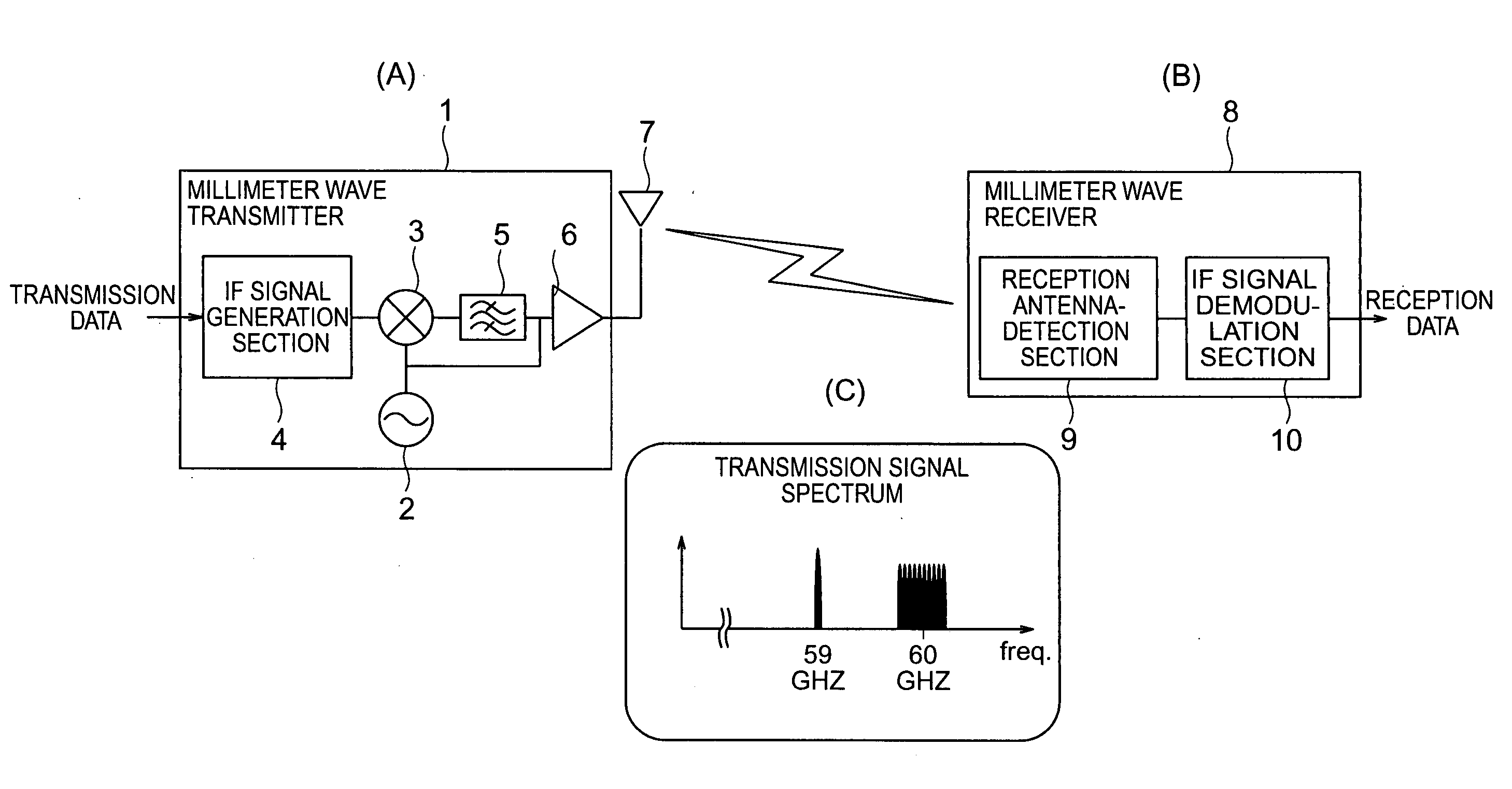
[0013] Sections (A) and (B) of FIG. 1 are diagrams showing an example configuration of a radio system according to a first embodiment of the present invention. A millimeter wave transmitter 1 includes an IF signal generation section 4 for modulating input data and outputting an IF-band modulated signal. The IF-band modulated signal is output to a mixer 3, to which a local oscillation signal is supplied from a local oscillator 2. The mixer 3 obtains a product of the IF-band modulated signal and the local oscillation signal. The thus-obtained output is passed through a band-pass filter 5 so as to remove unnecessary wave components therefrom. Thus, a radio-frequency (RF)-band modulated signal is obtained. Subsequently, a portion of power of the local oscillation signal used for the frequency conversion is added to the RF-band modulated signal. A resultant radio signal is amplified by means of an amplifier 6 and is then transmitted from an antenna 7. By virtue of the above-described tra...
second embodiment
[0015] Sections (A) and (B) of FIG. 3 are diagrams showing an example configuration of a radio system according to a second embodiment of the present invention. A millimeter wave transmitter and a millimeter wave receiver are provided in each of two stations which perform communications therebetween, whereby bi-directional radio communications are enabled. As in the first embodiment, a mixture signal containing a radio-frequency (RF)-band modulated signal and a local oscillation signal is transmitted from the transmitter of the first station. At the second station, the mixture signal is detected by the reception antenna-detection section, which the feature of the present invention, and the output of the reception antenna-detection section is input to an IF signal demodulation section so as to demodulate the reception data. At the same time, a mixture signal from the second station is received by the first station, and the reception data are demodulated.
PUM
 Abstract
Description
Claims
Application Information