Double compression unloadable screw system

a screw system and screw technology, applied in the field of bone surgery apparatus and method, can solve the problems of reducing the chance of bone screw failure, and achieve the effects of improving the compression of bone fragments, strengthening the bone screw, and increasing the compression

Inactive Publication Date: 2005-06-30
MILLENNIUM MEDICAL TECH INC
View PDF17 Cites 112 Cited by
  • Summary
  • Abstract
  • Description
  • Claims
  • Application Information

AI Technical Summary

Benefits of technology

[0005] The present invention provides an apparatus and method for both improving the compression of the bone fragments as well as strengthening of the bone screw. It includes a screw shaft with threads on the proximal and distal ends to unite the bone fragments, a head which threads over the proximal end of the screw shaft and provides increased compression on the bone fragments and a sleeve which slides or threads around the bone screw and provides reinforcing strength. The compression head and the strengthening sleeve may be a single unit or may be two distinct components. Therefore, the invention has the advantage that the combined head and sleeve, or the head and sleeve individually, can be removed in the future after initial insertion of the assembly.
[0006] The compression head and the sleeve serve to increase the compression pressure on the bone fragments and to decrease the likelihood of screw failure. After the screw shaft is inserted through the bone fragments to unite them under pressure, the reinforcing sleeve (or head and sleeve combination) slides or threads around the proximal end of the inserted screw shaft. It is of a length sufficient to extend across the region of the screw shaft that is under stress and prone to failure. The sleeve thus provides reinforcing strength to this area of the bone screw to decrease the likelihood of future bone screw breakage. The compression head (if not part of a head and sleeve combination) is then threaded onto the proximal threaded end of the bone screw. In this way, the head (or the head portion of the combined head and sleeve) creates further compression across the fracture line such that there is a double compression of the bone fragments, which is desirable for bone healing.
[0007] The removable nature of the compression head and reinforcing sleeve can serve various purposes. For example, the sleeve may be made of a material which reveals signs of stress when imaged, such as by an x-ray. When a stressed sleeve is thus detected, it can then be removed and replaced by a new sleeve. The new sleeve then continues to provide reinforcement to the bone screw and further decreases the chance of bone screw failure. Such a sleeve therefore provides protection against bone screw failure in multiple ways. The sleeve provides physical reinforcement to the screw when initially installed. It also prevents bone screw failures by revealing, through imaging or other manner, the need for replacement of the stressed sleeve with a new sleeve.
[0008] The system can also be used to provide bone dynamization to promote bone healing. After insertion of the bone screw assembly and a period of bone regrowth under static conditions, either the compression head, the sleeve or both may be moved or removed. Removal of these elements decreases the compression on the bone fragments and allows some increased mobility of the bone fragments. This change in conditions may be used to stimulate continued bone re-growth and strengthening after initial re-growth has occurred.

Problems solved by technology

The new sleeve then continues to provide reinforcement to the bone screw and further decreases the chance of bone screw failure.

Method used


Image

  • Double compression unloadable screw system
  • Double compression unloadable screw system
  • Double compression unloadable screw system

Examples


Embodiment Construction

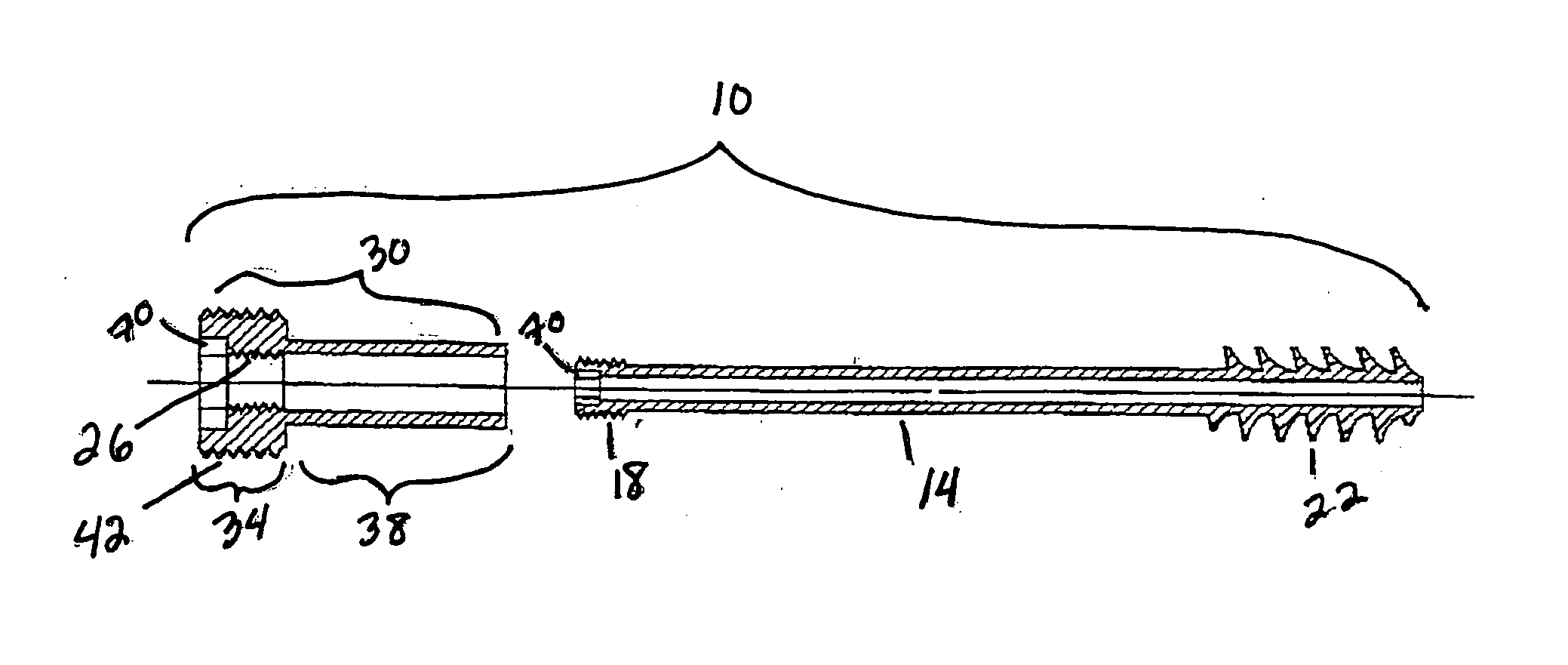
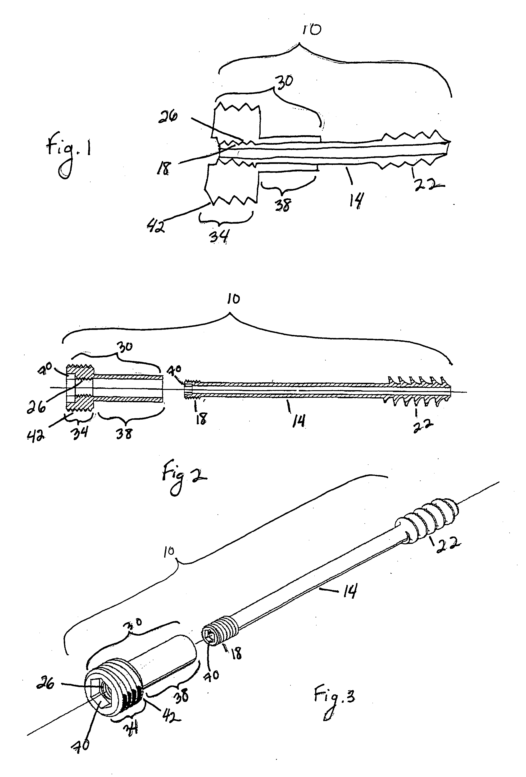
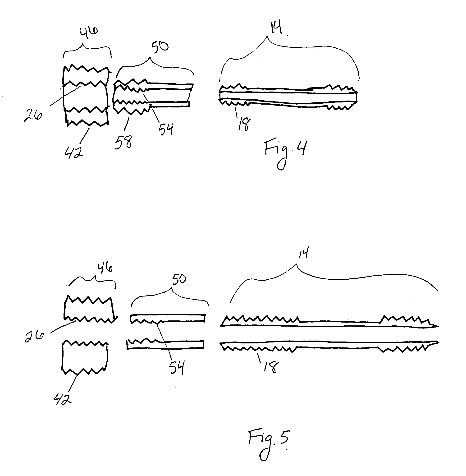
[0016] The bone screw assembly of the present invention is shown in FIGS. 1 through 7. As shown in FIGS. 1 through 3, the bone screw assembly 10 includes a screw shaft 14 having an elongate wall structure and external threads 18, 22 at the proximal and distal ends, respectively. The distal end of the screw shaft is shaped to allow it to penetrate the bone. The screw shaft 14 may be partially or fully canulated or may be solid. The proximal screw threads 18 are shaped to engage the internal threads 26 of the compression unit 30. The distal screw threads 22 are shaped to engage the distal bone fragments and may comprise any of a plurality of functional patterns / shapes.

[0017] The compression unit 30 is shaped to advance along and around a portion of the screw shaft 14. The compression unit 30 includes a compression unit head 34 and a compression unit sleeve 38. The proximal first portion of the compression unit 30 is the compression unit head 34. The compression unit head 34 includes ...


PUM


Abstract

A bone screw assembly for joining bone fragments having a screw shaft, a compression head and a sleeve. The compression head has external threads for providing double compression of the bone fragments. The sleeve extends along and around the screw shaft to provide reinforcing strength and alignment to the screw.

Description

PRIORITY [0001] This application claims priority to Provisional Application No. 60 / 466,498 filed Apr. 29, 2003.FIELD OF THE INVENTION [0002] The invention generally relates to an apparatus and method of bone surgery. In particular, this invention is for uniting bone fragments, such as in a fractured hip. BACKGROUND OF THE INVENTION [0003] Hip fractures commonly occur through the neck of the femur and less frequently through the femoral head. Surgical repair of such fractures involves insertion of a screw from the lateral proximal femur, through the neck of the femur and into the femoral head. This results in uniting of the bone fragments under a certain amount of compression and allows for bone healing. These screws commonly have threads at the proximal and distal ends and have a central portion with no threads. The result is that the distal threads engage the most internal bone to be joined and the proximal threads engage the most proximal portion of bone to be joined, pulling toge...

Claims


Application Information

Patent Timeline
Patent Type & Authority Applications(United States)
IPC IPC(8): A61B17/74A61B17/86A61F2/30
CPCA61B17/8685A61B17/742
Inventor KYLE, RICHARD F.
Owner MILLENNIUM MEDICAL TECH INC
Why Eureka
Try Eureka