Intervertebral prosthesis

a technology of intervertebral bone and prosthesis, which is applied in the field of osteogenic interbody fusion implant devices, can solve the problems of inability to biocompatible material from which the fusion graft is made, chronic and/or debilitating back pain, and nerves passing near the affected area may be compressed and consequently irritated, so as to promote the fusion of adjacent vertebra

Inactive Publication Date: 2005-06-30
RHAUSLER
View PDF37 Cites 121 Cited by
  • Summary
  • Abstract
  • Description
  • Claims
  • Application Information

AI Technical Summary

Benefits of technology

[0020] In yet a further embodiment of an intervertebral prosthesis in accordance with the present invention, the prosthesis comprises a single tubular outer body portion having a plurality of holes and barbs on the outer cylindrical surface thereof and an axial bore. The barbs are elastically deformable. The plurality of holes in the surface thereof extend inwardly to the axial bore. The axial bore contains a bone graft material. In operation, a hole is drilled between adjacent vertebrae and the tubular outer body portion is i

Problems solved by technology

When one or more disks degenerate through accident or disease, nerves passing near the affected area may be compressed and are consequently irritated.
The result may be chronic and/or debilitating back pain.
In addition, the material from which the fusion graft is made should be biocompatible.
Unfortunately, most prior art implants do not fulfill one or more of these criteria for an ideal interbody fusion graft.
For example, many of the implants, such as the one described in U.S. Pat.

Method used


Image

  • Intervertebral prosthesis
  • Intervertebral prosthesis
  • Intervertebral prosthesis

Examples


Embodiment Construction

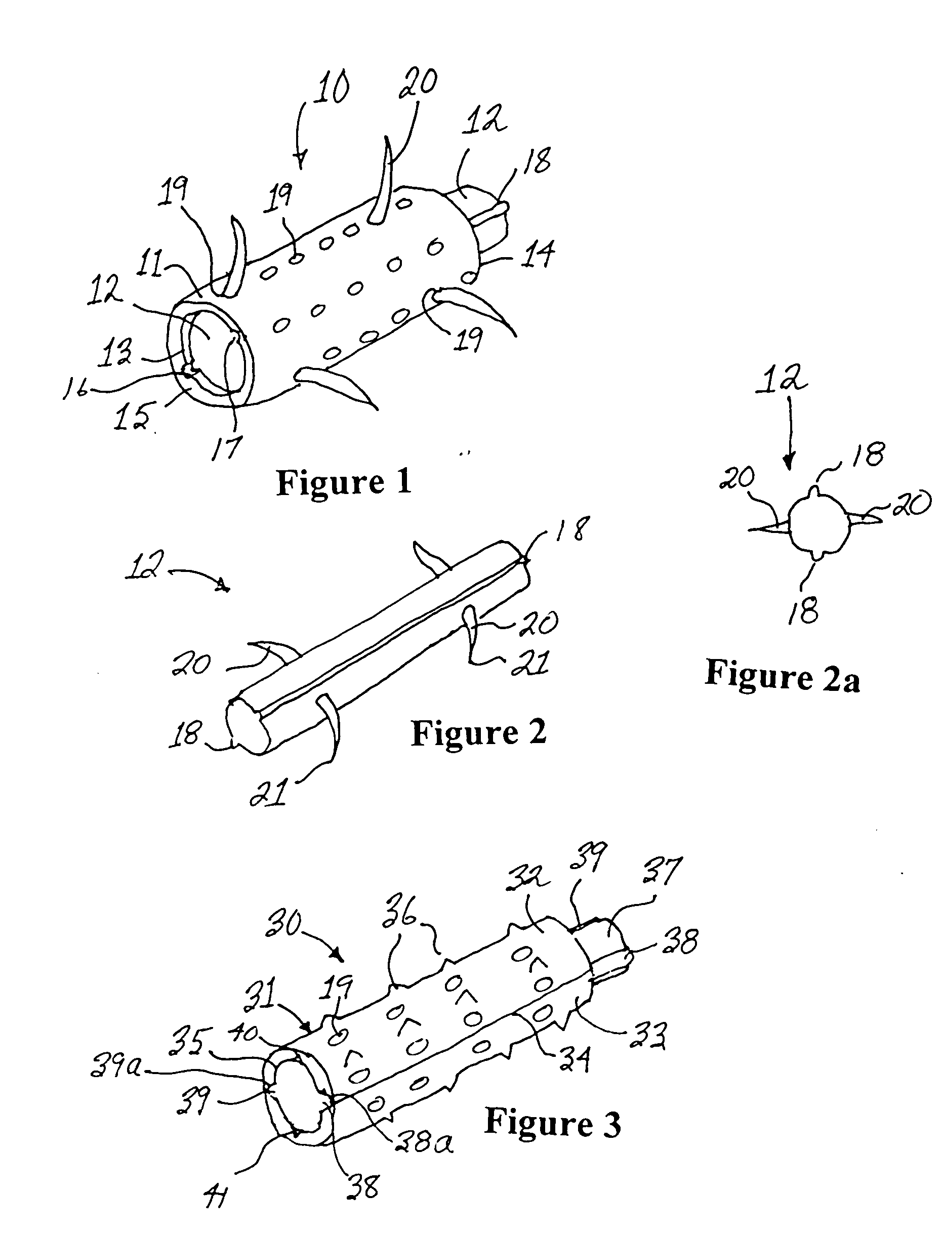
[0038] With reference to FIG. 1, the expandable intervertebral prosthesis 10 in accordance with a first preferred embodiment of the present invention comprises a tubular outer body portion 11 with an expansion cylinder 12 slidably disposed within an axial bore 13 in the tubular outer body portion 11. The expandable intervertebral prosthesis 10 has a proximal end 14 and a distal end 15. The wall of the tubular outer body portion has a plurality of holes 19 therein. The cylindrical axial bore 13 is coextensive with the length of the tubular outer body portion 11. The expansion cylinder 12 having a guide track 18 and a plurality of elastically deformable barbs 20 disposed along the length thereof is shown in greater detail in FIG. 2.

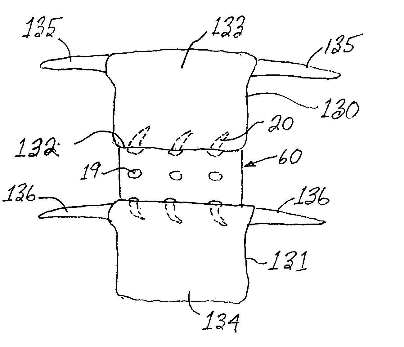
[0039] In order to use the embodiment of the expandable intervertebral prosthesis indicated at numeral 10, a hole is first drilled between adjacent vertebrae in a direction substantially transverse to the direction of the spine, the hole being centered bet...


PUM

PropertyMeasurementUnit
Pseudoelasticityaaaaaaaaaa

Abstract

An expandable intervertebral prosthesis includes a bone graft implant member dimensioned for insertion within an intervertebral space defined between adjacent vertebrae, thereafter adapted to vertically elevate and expand a plurality of barbs into the surrounding bone. The expandable intervertebral prosthesis has a tubular outer body portion having an axial bore with an enlarged proximal end and an exterior surface dimensioned to fit snugly within the space, and a barbed expansion cylinder slidably or rotatably mounted within the axial bore. The tubular outer body portion of the expandable intervertebral prosthesis has a plurality of longitudinal slots or holes in the wall thereof to allow the expansion and retraction of the expansion cylinder's barbs into or out of the surrounding bone. The barbs on the expansion cylinder may be elastically deformed from a normal, retracted configuration to a locking, splayed configuration wherein the outer ends of the barbs extend outwardly through the slots and exterior surface of tubular outer body to penetrate the surrounding bone as the expansion cylinder is moved. The expansion cylinder and, in one embodiment, the exterior surface of the tubular outer body portion, have a plurality of barbs disposed in circumferentially spaced relation about the body and positioned in various angles and positions respect to the axial bore. In another embodiment, the intervertebral prosthesis includes an elevating cylinder rotatably mounted within a frangible tubular outer body portion. The elevating cylinder has one or more detent positions that expand and vertically elevate the frangible tubular outer body portion of the intervertebral prosthesis body upon rotation thereof.

Description

BACKGROUND OF THE INVENTION [0001] 1. Field of the Invention [0002] The present invention relates to an osteogenic interbody fusion implant device and, more particularly, to a non-threaded intervertebral bone implant having a plurality of expandable barbs configured to facilitate securement of the implant within the intervertebral space. [0003] 2. Prior Art [0004] The spine is a flexible column formed of a plurality of bones called vertebra. The vertebrae are hollow and piled one upon the other, forming a strong hollow column for support of the cranium and trunk. The hollow core of the spine houses and protects the nerves of the spinal cord. The different vertebrae are connected to one another by means of articular processes and intervertebral, fibro-cartilaginous bodies. [0005] The intervertebral fibro-cartilages are also known as intervertebral disks and are made of a fibrous ring filled with pulpy material. The disks function as spinal shock absorbers and also cooperate with syno...

Claims


Application Information

Patent Timeline
IPC IPC(8): A61F2/00A61F2/02A61F2/28A61F2/30A61F2/44A61F2/46
CPCA61F2/446A61F2310/00011A61F2002/2835A61F2002/30062A61F2002/30092A61F2002/30235A61F2002/30364A61F2002/30367A61F2002/3055A61F2002/30556A61F2002/30579A61F2002/30601A61F2002/30784A61F2002/30841A61F2002/30975A61F2002/4619A61F2002/4627A61F2210/0004A61F2210/0014A61F2220/0033A61F2230/0069A61F2250/0009A61F2/4611
Inventor ENAYATI, ALBERT
Owner RHAUSLER
Why Eureka
Try Eureka