Patello-femoral joint arthroplasty

Inactive Publication Date: 2005-06-30
DEPUY PROD INC
View PDF29 Cites 26 Cited by
  • Summary
  • Abstract
  • Description
  • Claims
  • Application Information

AI Technical Summary

Benefits of technology

[0016] The present invention address the above cited need, as well as others, by providing a prosthetic patellar bearing surface that includes first and second femoral engaging surfaces disposed between first and second edge surfaces, the first and second edge surfaces being rounded, or otherwise having a gradual transition from a nearly backward (or posterior) facing portion to a nearly

Problems solved by technology

The lack of abrupt corners reduces the likelihood of s

Method used


Image

  • Patello-femoral joint arthroplasty
  • Patello-femoral joint arthroplasty
  • Patello-femoral joint arthroplasty

Examples


Embodiment Construction

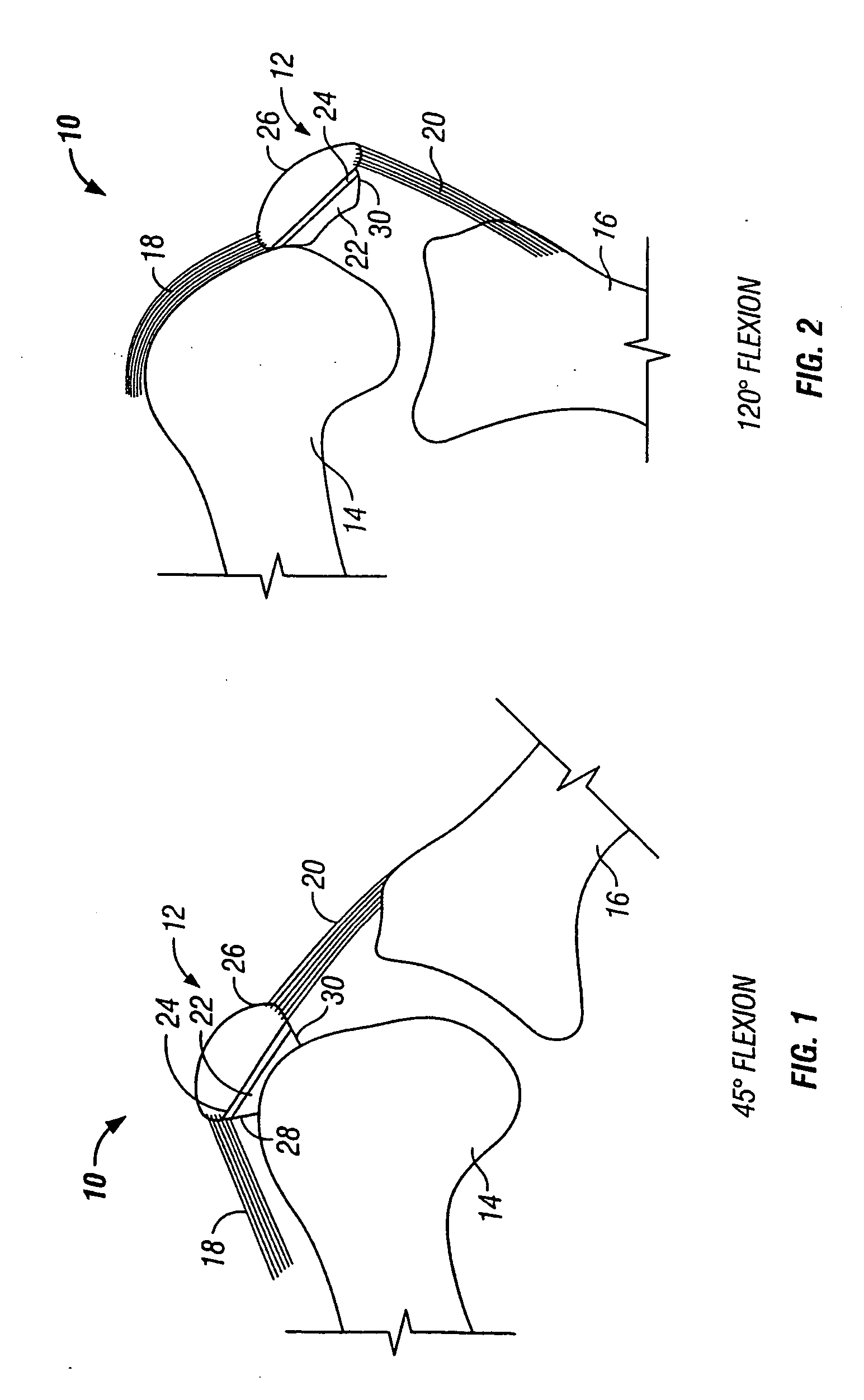
[0040]FIGS. 1 and 2 show side fragmentary views of a knee joint 10 in which an exemplary prosthesis arrangement 12 according to the invention has been implanted. FIG. 1 shows the knee joint 10 in approximately 45 degrees of flexion while FIG. 2 shows the knee joint 10 in approximately 120 degrees of flexion.

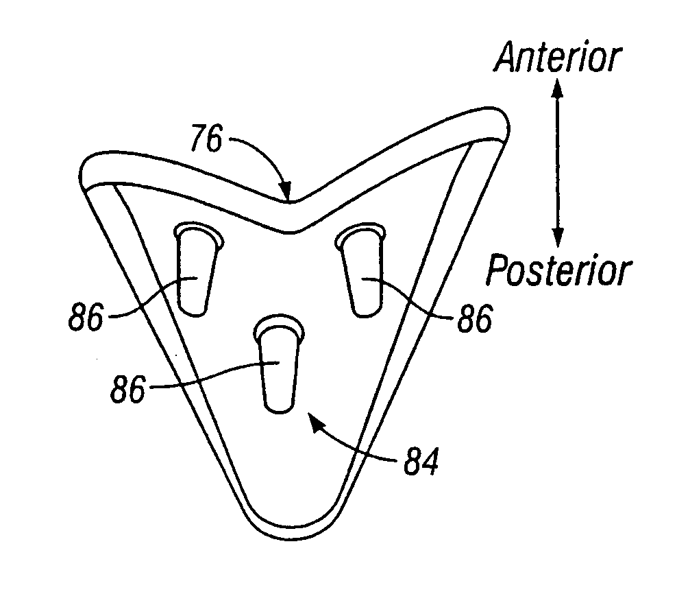
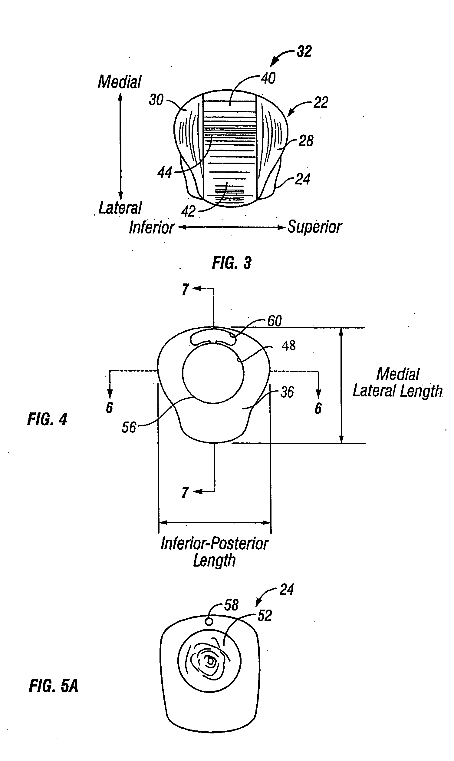
[0041] In addition to the prosthesis arrangement 12, the knee joint 10 shown in FIGS. 1 and 2 includes a portion of a femur 14, a portion of a tibia 16, quadricep connective tissue 18 and a patellar ligament 20. The prosthesis arrangement 12 further includes a bearing element 22, a base24 and natural patellar bone tissue 26. The bearing element 22 is secured to the base 24 such that partial rotation between the bearing element 22 and the base 24 may occur. The base 24 is securely affixed to the patellar bone tissue 26. The patellar bone tissue 26 is naturally affixed between the quadricep connective tissue 18 and the patellar ligament 20. In accordance with one aspect of the pre...


PUM


Abstract

A prosthetic patellar component includes a base and a bearing element. The base is operable to be affixed to an outer patellar surface. The bearing element includes first and second femoral engaging surfaces disposed between first and second edge surfaces and separated by a convex peak. The first and second edge surfaces include a gradual, or rounded, transition from a nearly posterior facing portion to a nearly superior or inferior facing portion, with adjacent surface portions having a relative angular displacement of less than about 30 degrees. The inferior-superior dimension is at least approximately 90% of the medial-lateral dimension. The femoral implant includes a medial bearing surface, a lateral bearing surface and a channel disposed therebetween. The femoral implant further includes a posterior surface having a maximum slope in medial-lateral cross-section of less than about 42 degrees to reduce the requirements for bone removal.

Description

REFERENCE TO RELATED APPLICATION [0001] This application is a continuation of co-pending application Ser. No. 10 / 212,853, filed on Aug. 6, 2002, which in turn claims priority to U.S. Provisional Application Ser. No. 60 / 310,527, entitled “Femoral Implant for Patello-Femoral Joint Arthroplasty and Associated Surgical Method”, filed on Aug. 7, 2001. The disclosures of each of the above-identified provisional and utility patent applications are hereby totally incorporated by reference in their entirety.FIELD OF THE INVENTION [0002] The present invention relates generally to prosthetic patello-femoral joint assemblies, and more particularly, to individual components of such prosthetic assemblies and associated surgical methods of implantation. BACKGROUND OF THE INVENTION [0003] The knee joint is a frequent place for joint damage, and the loss of normal (i.e. relatively pain-free) ambulatory function is a frequent result of such damage. Damage to the knee joint can occur as a result of an...

Claims


Application Information

Patent Timeline
IPC IPC(8): A61B17/17A61F2/30A61F2/38A61F2/46
CPCA61B17/1764A61B17/1767A61F2/30767A61F2/3877C12Y203/02015A61F2002/30892A61F2002/4631A61F2002/4681A61F2/461
Inventor MERCHANT, ALAN C.
Owner DEPUY PROD INC
Why Eureka
Try Eureka