Server, data processing system, and method of data processing

a data processing system and server technology, applied in the field of server and data processing system, can solve the problems of user not paying attention to the access status of their display, preventing the client terminal device from providing the user with and preventing the user from paying attention to the access status on the display, so as to achieve a pleasant working environment

Inactive Publication Date: 2005-06-30
PANASONIC CORP
View PDF3 Cites 5 Cited by
  • Summary
  • Abstract
  • Description
  • Claims
  • Application Information

AI Technical Summary

Benefits of technology

[0006] With the structure as described above, the output unit produces output of the data only when the access status data satisfies the predetermined condition. Accordingly, the server provides the data representing the access status and the like of the server only when the users need it by properly setting the predetermined condition, thereby avoiding the problem of sending the data when not required by the users. As a result, the server can provide the users, for instance, with pleasant working environment.

Problems solved by technology

On the other hand, it is considered in many cases that users become accustomed to display of access status (i.e., state of congestion) of a server in a server-client system if the access status is displayed at all the time in client terminal devices and the like, and this often causes the users not to pay attention to the access status in their displays.
However, the users often desire to know the access status data from the server when their access to the server becomes congested.
On the other hand, if the server sends the access status data of it at all the time, it gives rise to a problem that the client terminal devices display the access status even when the users do not want it.
There is also another problem that a space occupied for displaying the access status reduces an area of a monitor screen for other information and it prevents the client terminal devices from providing the users with pleasant working environment (i.e., display environment) if the access status of the server is displayed in the monitors and the like even when the users do not need it.

Method used


Image

  • Server, data processing system, and method of data processing
  • Server, data processing system, and method of data processing
  • Server, data processing system, and method of data processing

Examples


first embodiment

[0024] Referring now to the accompanying drawings, description is provided of a server according to the first embodiment of the present invention.

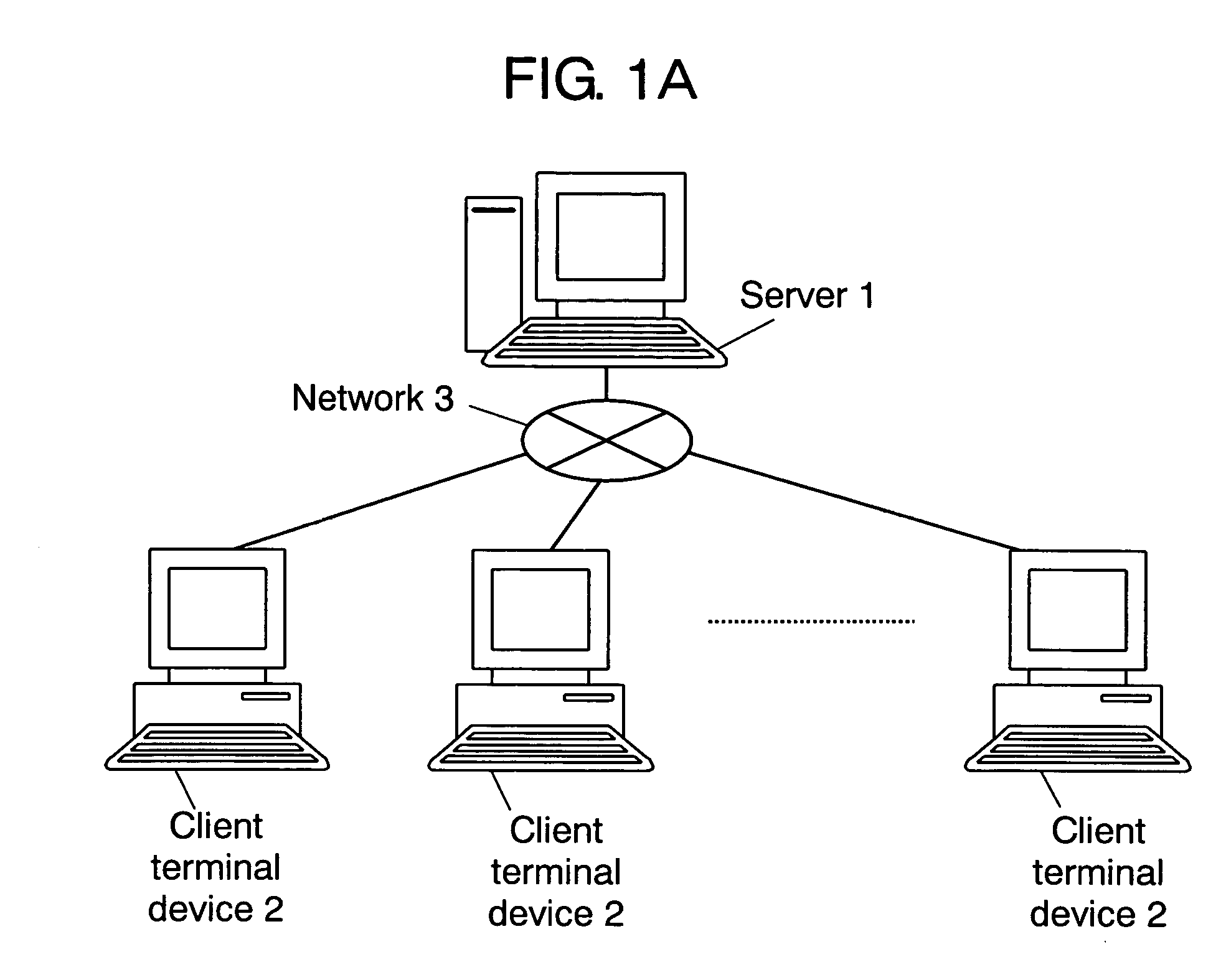
[0025]FIG. 1A is a schematic illustration showing an architecture of a server client system according to the first embodiment. In FIG. 1A, the server client system of the first embodiment comprises server 1 and a plurality of client terminal devices 2. Server 1 and these client terminal devices 2 are connected to telecommunications network 3 through any a cable and wireless connection. This telecommunications network may be the Internet, Intranet, and the like, for instance. The server client system in this first embodiment can be a server client system in the LAN, or it can be a system comprising a server such as a web server in the WAN of the Internet and the like and a data processor (i.e., the client terminal device) having a browser and the like for making access to the server.

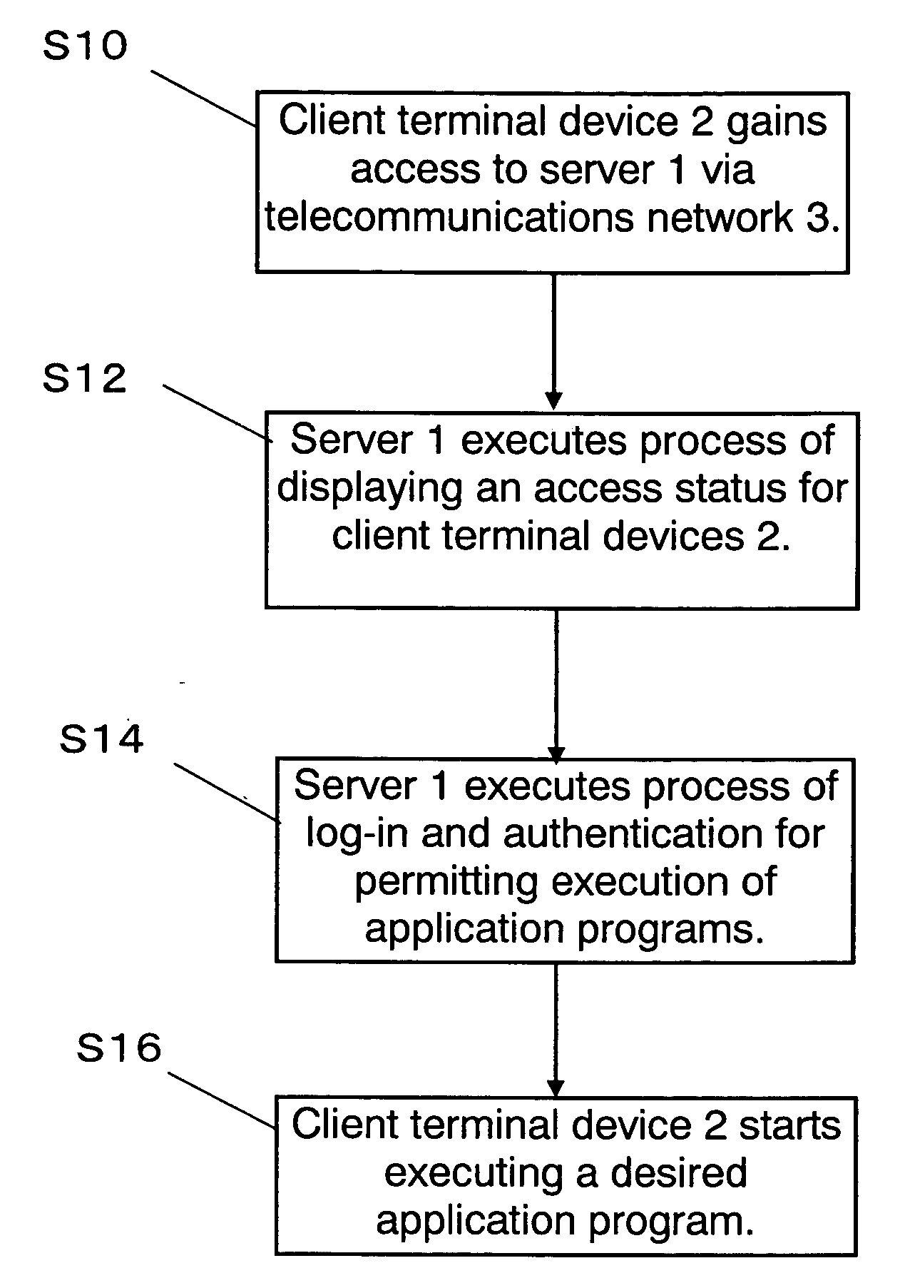
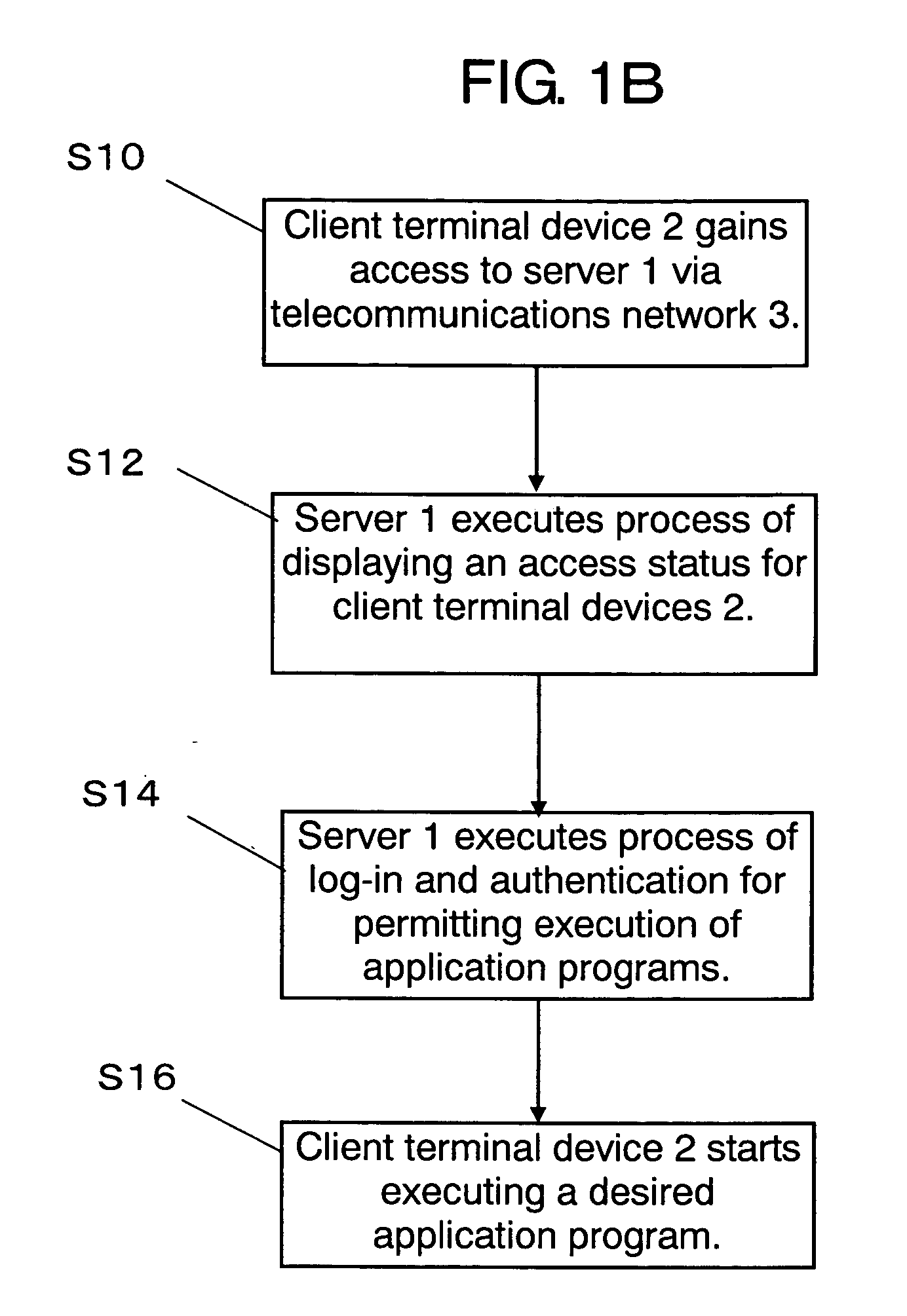
[0026]FIG. 1B is a flowchart showing a principal process...

first concrete example

[0045] In this first concrete example, description is provided of a case in which output unit 15 outputs a data to all client terminal devices 2 being logged-in, and execution processing unit 11 does not accept a new log-in when it determines that a number of log-ins exceeds the predetermined threshold value.

[0046] Execution processing unit 11 accepts log-ins from the plurality of client terminal devices 2 and executes processes in response to commands from the logged-in client terminal devices 2. FIG. 4 is a table showing an example of log-in data retained in execution processing unit 11. In FIG. 4, a terminal ID for identifying client terminal device 2 and a log-in time indicating the time a user has logged in are shown in a manner to correlate with a user ID that identifies the user. When the user logs out, execution processing unit 11 deletes the log-in data related to that user from the record.

[0047] It is assumed that acquiring unit 12 acquires a number of log-ins kept by cl...

second concrete example

[0054] In this second concrete example, description is provided of a case in which output unit 15 outputs a data to all client terminal devices 2 being logged in, and execution processing unit 11 logs out certain client terminal device 2 among the client terminal devices 2 kept logged in, when it determines that the number of log-ins exceeds the predetermined threshold value. Since operation up to the process of transmitting the output data from output unit 15 to client terminal devices 2 is analogous to the first concrete example, details of it is skipped.

[0055] Execution processing unit 11 refers to the log-in data, and logs out one of client terminal devices 2 that has logged in earliest when it receives information to the effect that the number of log-ins exceeds the predetermined threshold value of “40” from determining unit 13. This client terminal device 2 is the one identified by terminal ID “C001” in the log-in data table shown in FIG. 4.

[0056] To be more specific, execut...


PUM


Abstract

A server according to this invention comprises an execution processing unit for receiving access of a plurality of client terminal devices and executing processes according to a command given by the client terminal devices, an acquiring unit for acquiring an access status data representing information showing access status of the client terminal devices in the execution processing unit, a determining unit for determining whether the access status data satisfies a predetermined condition, and an output unit for producing an output of data based on the access status data when the determining unit determines that the access status data satisfies the predetermined condition. A structure discussed above can provide the server with a capability of outputting data on the access status thereof only when output of the data is needed.

Description

TECHNICAL FIELD [0001] The present invention relates to a server and the like device for receiving access from a plurality of client terminal devices. BACKGROUND OF THE INVENTION [0002] There have been hitherto developed certain systems that automatically measure a degree of congestion in client receiving windows such as a call center, and make them available through the network, as has been disclosed in Japanese Patent Unexamined Publication, No. 2002-368897 (page 7 through page 9, and FIG. 1, etc.). [0003] On the other hand, it is considered in many cases that users become accustomed to display of access status (i.e., state of congestion) of a server in a server-client system if the access status is displayed at all the time in client terminal devices and the like, and this often causes the users not to pay attention to the access status in their displays. It is also thought that there is no need for the server to provide the access status to the users of the server when client te...

Claims


Application Information

Patent Timeline
Patent Type & Authority Applications(United States)
IPC IPC(8): G06F15/177H04L29/06H04L29/08
CPCH04L67/325H04L63/102H04L67/62
Inventor SHIBA, MASAYUKI
Owner PANASONIC CORP
Why Eureka
Try Eureka