Adaptive deterministic grouping of blocks into multi-block units

a technology of adaptive deterministic grouping and blocks, applied in the direction of memory adressing/allocation/relocation, input/output to record carriers, instruments, etc., can solve the problems of cell no longer usable, floating gate eventually wears out and breaks down, and the number of limitations

Inactive Publication Date: 2005-06-30
SANDISK TECH LLC
View PDF19 Cites 310 Cited by
  • Summary
  • Abstract
  • Description
  • Claims
  • Application Information

AI Technical Summary

Benefits of technology

[0011] The various aspects of the present invention overcome these and other limitations found in the prior art for the linking of physical memory structures into composite logical structures. In the primary embodiment of the present invention, techniques are presented for the formation of metablock structure in flash memories. According to a first aspect of the present invention, the linking of block into metablocks is updated to accommodate defective portions of the memory. A system for maintaining a defect map includes a defect map structure for tracking the existence of factory and grown defects in a nonvolatile memory system that is organized into metablocks. A method for maintaining a defect map makes use of the defect map structure and the characteristics of a metablock. In one embodiment, the size of the defect map structure is equal to the parallelism of the nonvolatile memory system. In another embodiment, the remaining units of erase that cannot be assigned to a metablock will be kept in a list of spare units of erase for later use.

Problems solved by technology

One known problem with floating gate devices such as EEPROMs is that the floating gate eventually wears out and breaks down after a very large number of write, program and erase cycles.
When this happens, the cell is no longer usable and must be taken out of the list of available memory cells in the array.
Although this allows for the formation of metablocks and all of the blocks in a given metablock to be addressed by the same address, namely the address of the block in the first of the devices, it has a number of limitations.
For example, as the linking of blocks into metablocks is pre-determined in this fixed configuration, when a block goes bad, the metablock to which it belongs becomes bad despite the other blocks within it still being functional.

Method used


Image

  • Adaptive deterministic grouping of blocks into multi-block units
  • Adaptive deterministic grouping of blocks into multi-block units
  • Adaptive deterministic grouping of blocks into multi-block units

Examples


Embodiment Construction

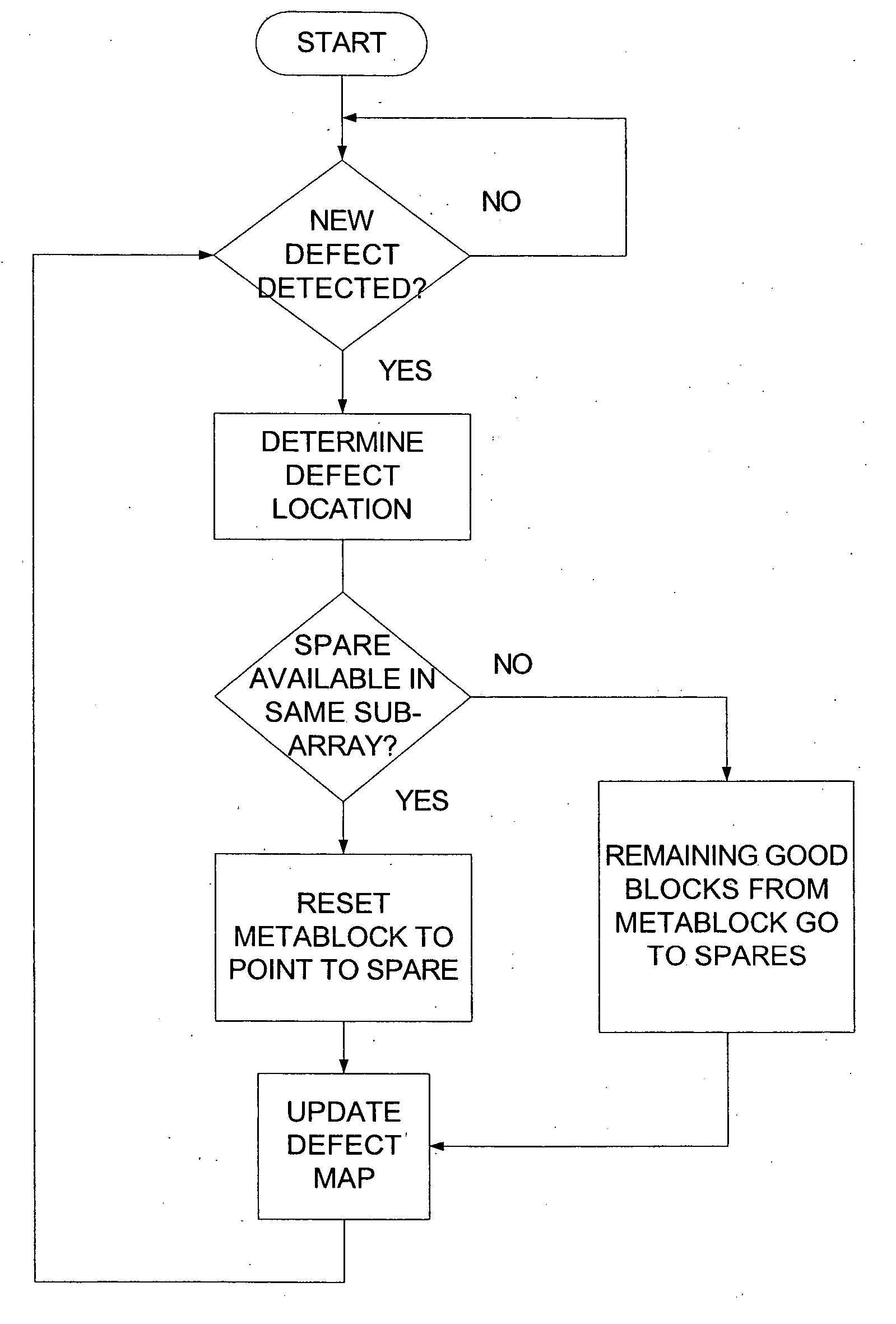
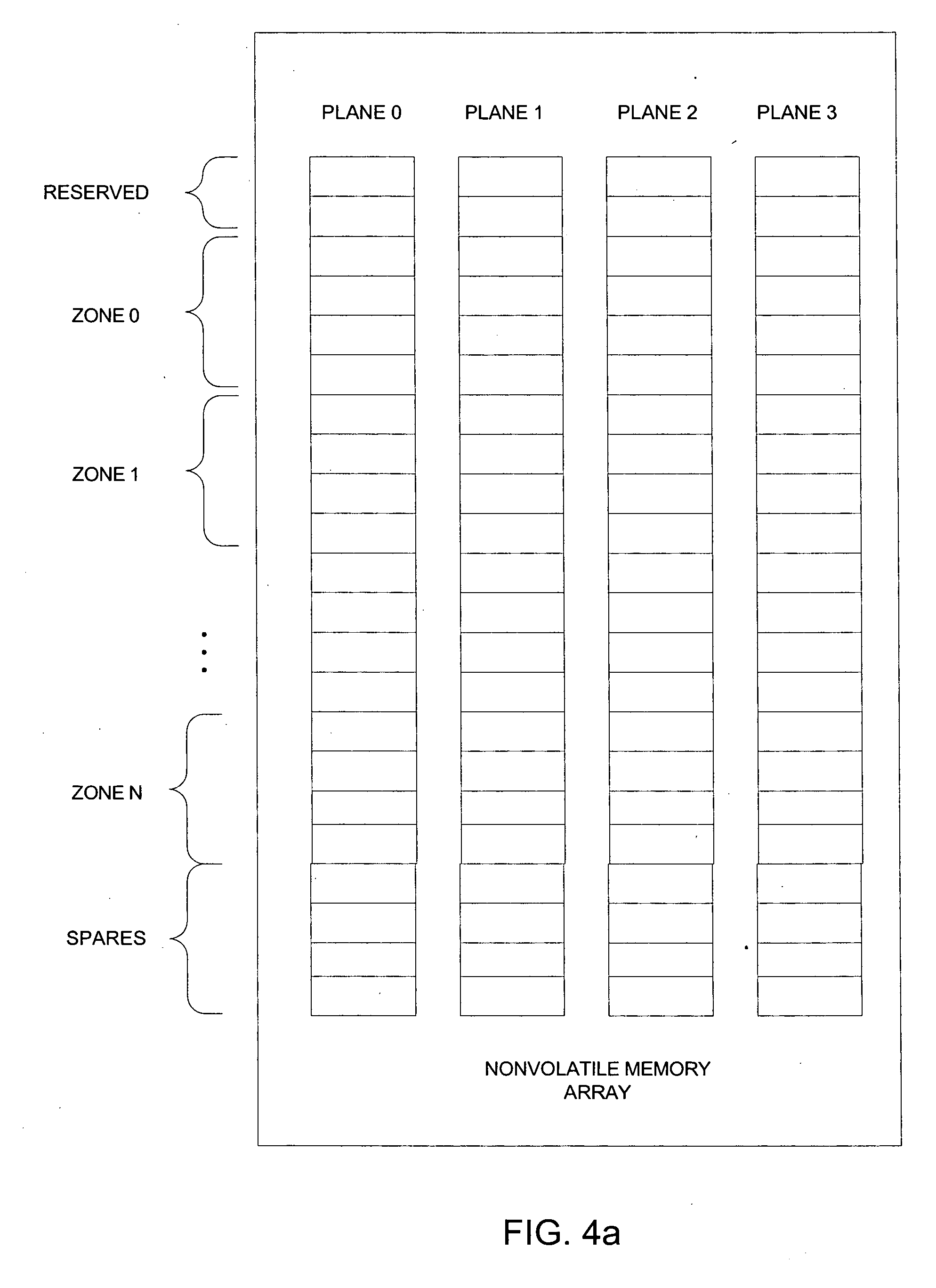
[0027] Generally, the memory system of the present invention maintains in its main non-volatile memory a record of the linking of blocks into multi-block metablock structures. This record contains a defect map of factory and grown defects in a map table that can be read into non-volatile memory on demand. This map is updated as grown defects are encountered and blocks are assigned to new locations. Metablocks are preferable formed by one block in each of several subarrays, or planes, and in this case, the grouping is done preferably with same-numbered blocks in each plane, with the exception of blocks that are marked bad and placed in the map. In one embodiment, the blocks are directly mapped to alternate blocks. Metablocks that would contain the defective block are then reformed with the alternate block in the corresponding plane. Rather than maintain a complete record of the linking of blocks into metablocks within the non-volatile memory, a “standard” linking can be based on an a...


PUM


Abstract

The present invention presents techniques for the linking of physical blocks of a non-volatile memory into composite logical structures or “metablocks”. After determining an initial linking of good physical blocks into metablocks, a record of the linking is maintained in the non-volatile memory where it can be readily accessed when needed. In one set of embodiments, the initially linking is deterministically formed according to an algorithm and can be optimized according to the pattern of any bad blocks in the memory. As additional bad blocks arise, the linking is updated using by replacing the bad blocks in a linking with good blocks, preferably in the same sub-array of the memory as the block that they are replacing.

Description

[0001] This application is related to U.S. patent application entitled “NON-VOLATILE MEMORY AND METHOD WITH BLOCK MANAGEMENT SYSTEM”, by Peter Smith, Alan Bennett, Alan Bryce, Sergei Gorobets, and Alan Sinclair with which it is filed concurrently and which is hereby incorporated by reference: FIELD OF THE INVENTION [0002] This invention relates generally to semiconductor non-volatile data storage systems, and more specifically, to a system and method for forming physical blocks into larger logical structures that accommodate defects in non-volatile data storage systems. BACKGROUND OF THE INVENTION [0003] Nonvolatile memory devices such as flash memories are commonly used as mass data storage subsystems. Such nonvolatile memory devices are typically packaged in an enclosed card that is removably connected with a host system, and can also be packaged as the non-removable embedded storage within a host system. In a typical implementation, the subsystem includes one or more flash device...

Claims


Application Information

Patent Timeline
Patent Type & Authority Applications(United States)
IPC IPC(8): G06F3/06G06F12/02G11C29/00
CPCG06F12/0246G11C29/808G11C29/76G06F2212/7201G06F2212/7208G06F3/06G06F12/00G06F12/02G11C29/00
Inventor GONZALEZ, CARLOS J.BRYCE, ALAN DOUGLASGOROBETS, SERGEY ANATOLIEVICHBENNETT, ALAN DAVID
Owner SANDISK TECH LLC
Why Eureka
Try Eureka