
Engine connecting rod for high performance applications and method of manufacture

a technology of connecting rods and high-performance engines, applied in the direction of process and machine control, mechanical control devices, instruments, etc., can solve the problems of increasing stress in the connecting rod, affecting engine performance, etc., and achieves the effect of simplifying and facilitating accurate and analyzed connecting rod design, and reducing the number of elements

Inactive Publication Date: 2005-07-07
WEAVER ROBERT R
View PDF10 Cites 11 Cited by
  • Summary
  • Abstract
  • Description
  • Claims
  • Application Information

AI Technical Summary

Benefits of technology

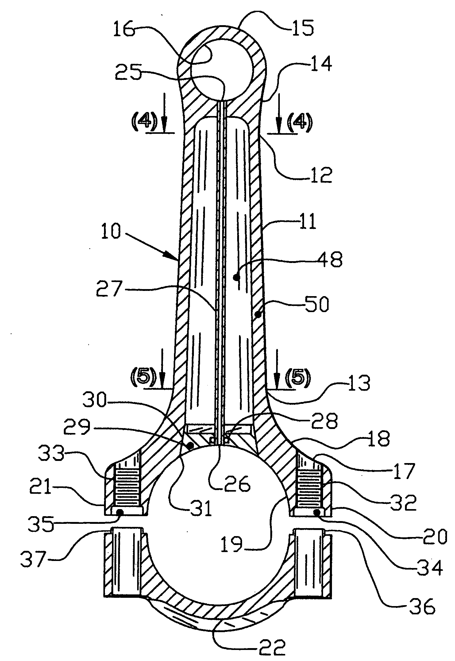
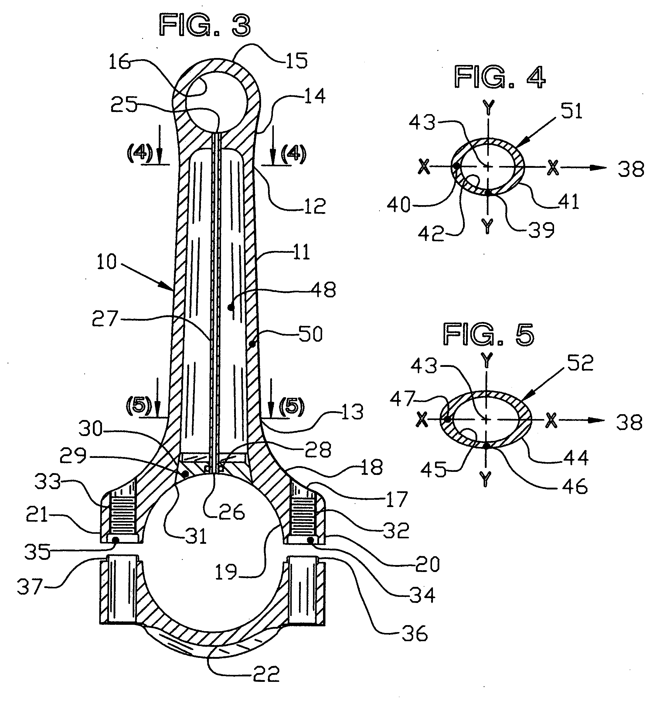
[0012] The present invention provides a connecting rod comprising a hollow beam member of near minimum cross-section area and mass achievable. It is preferred that this is accomplished by precise beam thin wall of variable blended thickness cross-sections having elliptical type or modified oval formation configured to smoothly distribute stress and eliminate stress concentration areas throughout the connecting rod. The elimination of stress concentrations lowers peak stress levels resulting in reliable performance at high engine RPM (Revolutions Per Minute) and improves fatigue life. Controlling and reducing stress levels and distribution patterns facilitates weight and mass reduction. This is important because weight reduction reduces inertia forces further lowering stress levels. Placement of beam defining cross-sections and section profile are defined with method to facilitate design and analysis of hollow beam connecting rod manufactured from high strength materials.
[0013] The primary objective of providing lower stress levels and lower reciprocating weight is to reduce inertia forces. Inertia forces affect engine performance and increase stress in connecting rods. Hollow rod beam weight reductions of 45 to 60 grams over competing solid beam connecting rods have occurred in designs. Reduction of 45 grams of reciprocating weight will reduce peak inertia force by about 400 pounds at peak RPM, determined in studies. Performance is improved by increasing compressive force by 400 pounds on the piston during the power stroke. This is possible because inertia force (400 lbs.) must be overcome during the early part of combustion by combustion pressure to push the piston during the power stroke.
[0014] Another objective is to provide a smooth aerodynamic shape to reduce effects of rod contact with the ambient oil particle environment and air occurring within an engine at high RPM.
[0016] An improvement of one embodiment of this invention is having a procedural embodiment to locate profile cross-section forms on the beam longitudinal axis to define the connecting rod beam surface. A further purpose is to reduce the number of elements required to define a connecting rod beam to a few cross-section profiles, generally two profiles placed on the beam longitudinal axis. The beam form defining and design may be accomplished using computer programs. This objective simplifies and facilitates accurate and analyzed connecting rod design. Computer programs which may be used are Computer Aided Design (CAD), Finite Element Analysis (FEA) and Computer Numerical Controlled (CNC) machining. Another advantage of this improvement is design files may be computer generated and transferred by electronic means directly to CNC manufacturing machines and facilities.

Problems solved by technology

Inertia forces affect engine performance and increase stress in connecting rods.

Method used


Image

  • Engine connecting rod for high performance applications and method of manufacture
  • Engine connecting rod for high performance applications and method of manufacture
  • Engine connecting rod for high performance applications and method of manufacture

Examples


Embodiment Construction

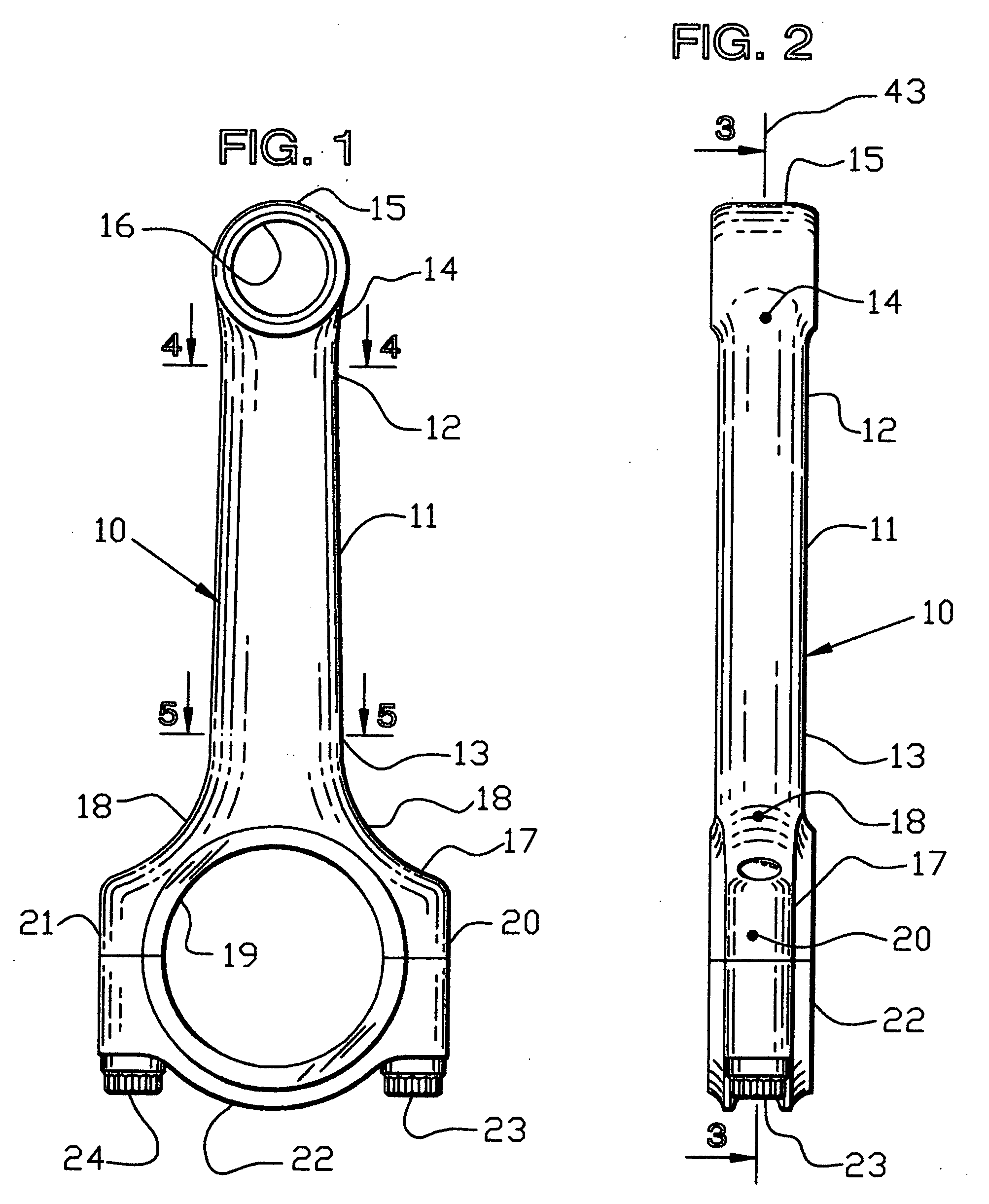
[0030] A general description being presented, with reference to FIG. 1 and FIG. 2 of the drawings there depicted a hollow connecting rod 10 for use in high performance engines. The connecting rod 10 comprising an elongate longitudinal beam member 11 having two opposite ends 12, 13 each forming a one-piece connection. Connection to first end 12 having blended arcuate sides 14, joining piston pin connecting boss member 15 having a round bearing surface 16, for cooperating with a piston pin (not shown). At beam member 11 opposite second end 13 is a crankshaft journal connecting member 17, having blended arcuate sides 18, including a round bearing surface 19 for cooperating with a bearing insert and crankshaft journal when secured thereto (not shown). Connecting member 17 having bolt boss 20, 21, secured thereto cap member 22 and bolts 23, 24. As noted in FIG. 1, beam cross-sections cut lines 4-4 and 5-5 define the beam member 11 by placement of profile cross-section placed at each cut ...


PUM

PropertyMeasurementUnit
Thicknessaaaaaaaaaa
Concentrationaaaaaaaaaa
Tensile propertiesaaaaaaaaaa

Abstract

An internal combustion engine connecting rod, having an embodiment defining a hollow beam member and a process of manufacture are disclosed. The improvement substantially reduces beam tensile and compressive stress levels through application of elliptical and oval beam sections, conserving reciprocating and rotating connecting rod weight required in high performance engine applications.

Description

CROSS-REFERENCE TO RELATED PATENT APPLICATIONS [0001] This is a continuation-in-part of pending U.S. patent application Ser. No. 10 / 079,150 filed Feb. 20, 2002, titled Engine Connecting Rod for High Performance Applications and Method of Manufacture. The benefit of U.S. Provisional Patent Application Ser. No. 60 / 270,279, filed Feb. 22, 2001, is claimed.BACKGROUND OF THE INVENTION [0002] 1. Field of the Invention [0003] The present invention relates to the field of high performance internal combustion engines pertaining to a connecting rod having a Hollow Beam construction providing a lighter and stronger connecting rod beam member, accomplished by originated elliptical type and eccentric circular segmented walled cross-sections. [0004] 2. Description of Background Information [0005] Hollow connecting rods have a history dating back to early automotive engines of the 1920's. Particularly, achieving notoriety in high performance engines. In the mid 1960's the Meyer and Drake, “Offy” r...

Claims


Application Information

Patent Timeline
IPC IPC(8): F01M11/02F16C7/02F16C33/10
CPCF01M11/02F01M2011/025Y10T74/2159F16C7/023F16C33/10F01M2011/027F16C2360/22
Inventor WEAVER, ROBERT R.
Owner WEAVER ROBERT R
Learn More