High performance dual-patch antenna with fast impedance matching holes

a dual-patch antenna and impedance matching technology, applied in the field of dual-patch antennas, can solve the problems of limited use scope of traditional antennas, large antenna size, and difficulty in dual-patch antennas, and achieve excellent impedance matching, high gain, and wide bandwidth

Inactive Publication Date: 2005-07-07
HON HAI PRECISION IND CO LTD
View PDF8 Cites 19 Cited by
  • Summary
  • Abstract
  • Description
  • Claims
  • Application Information

AI Technical Summary

Benefits of technology

[0008] A primary object, therefore, of the present invention is to provide an omni-directional dual-patch antenna with high gain, wide bandwidth, excellent impedance matching and compact size, for operating in wireless communications under IEEE 802.11b / g standard.
[0009] In order to implement the above object and overcomes the above-identified deficiencies in the prior art, the dual-patch antenna of the present invention comprises an air parch dielectric substrate, a top and a bottom radiating patches which are separately disposed on each side of the dielectric substrate, the two radiating patches having the same dimension and being parallel to each other, a feeding cable inserted between the two radiating patches, and a support portion. A plurality of matching holes is defined by both radiating patches and is provided for fast impedance match tuning and heat dissipation. The location of matching holes depends on the antenna length. The number of matching holes depends on the tuning range of the antenna length. The adding of matching holes speeds up the impedance matching procedure and optimizes the efficiency of impedance matching. Both patches (top and bottom) having the same dimension and holes makes the mass manufacturing of the antenna become fast and easy.

Problems solved by technology

Though the traditional patch antenna has much advantage mentioned above, a drawback is that it has a big ground portion resulting in a large size of the antenna.
Another drawback is that the radiating pattern of the traditional patch antenna is not omni-direction, thus the scope of the use of the traditional antennas is limited.
However, there are some difficulties with the dual-patch antenna.
First, the input impedance of the antenna is tuned by varying the location of the feed point, which cannot obtain excellent efficiency.
Second, the bandwidth of the antenna is narrow.
Usually, to increase the bandwidth of a patch antenna, the thickness of the dielectric substrate is increased, which easily results in impedance mismatching between the antenna and its feeding cable.
The impedance mismatching causes a portion of the feed power to be reflected to the signal source rather than to be radiated to the free space.
Third, the dielectric substrate of the traditional patch antenna will introduce insertion loss, which does not fit a high gain application.

Method used


Image

  • High performance dual-patch antenna with fast impedance matching holes
  • High performance dual-patch antenna with fast impedance matching holes
  • High performance dual-patch antenna with fast impedance matching holes

Examples


Embodiment Construction

[0019] Reference will now be made in detail to a preferred embodiment of the present invention.

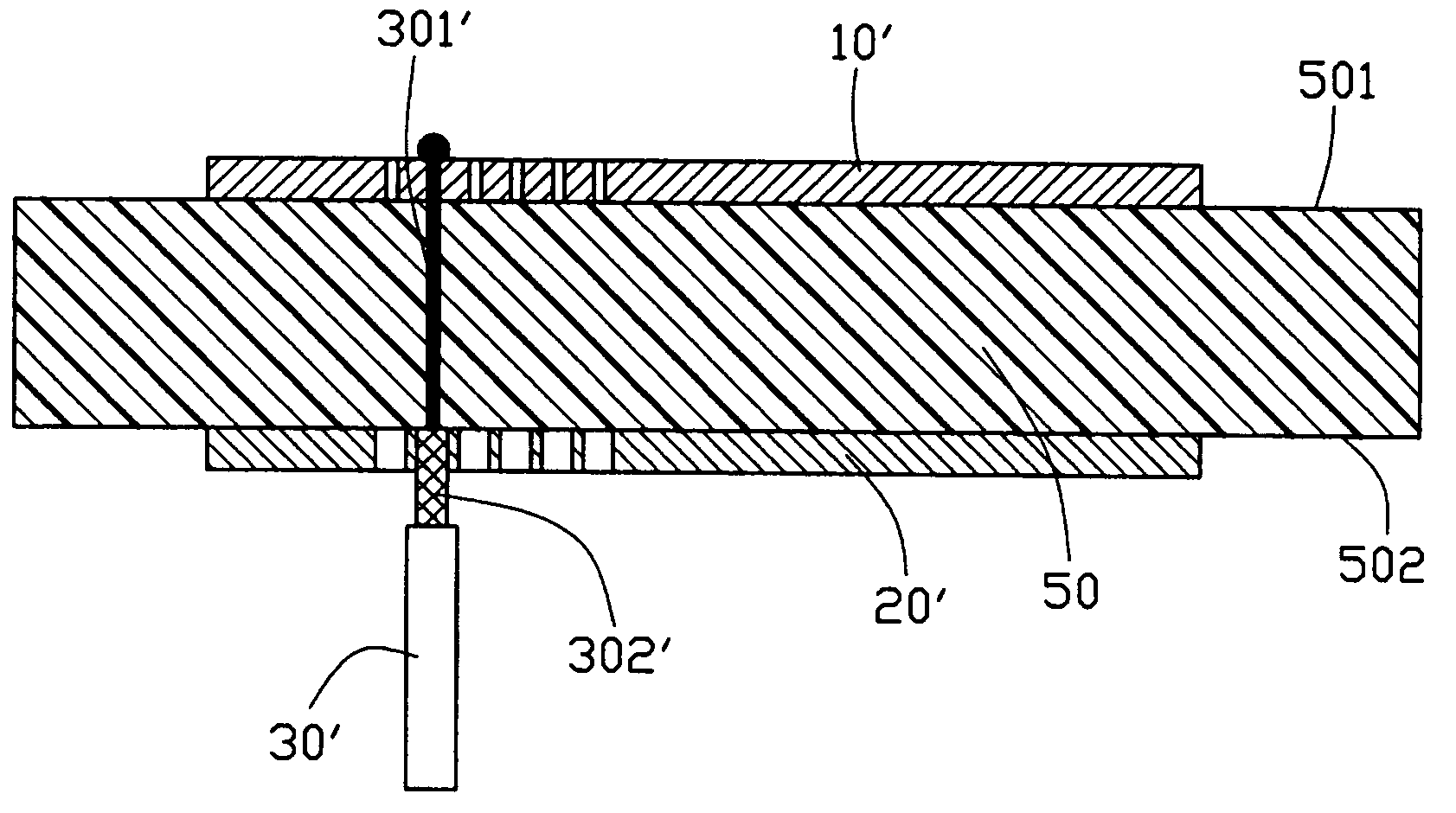
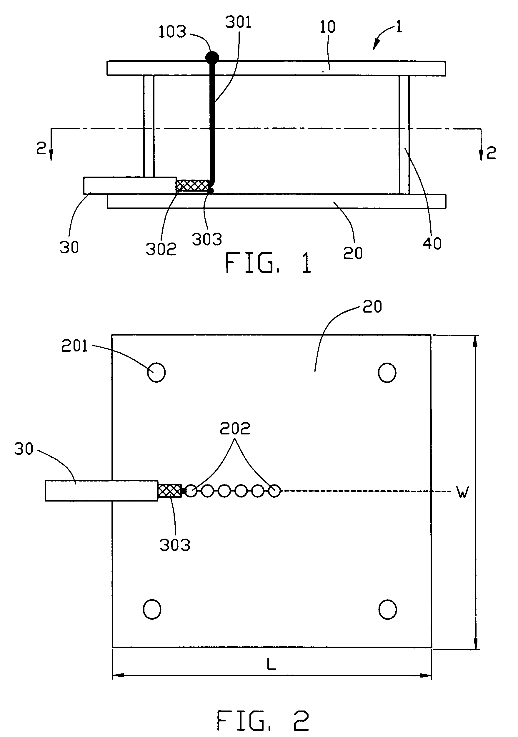
[0020] Referring to FIGS. 1-2, a dual-patch antenna 1 according to the present invention comprises a top radiating patch 10, a bottom radiating patch 20, a feeding cable 30, and a support portion 40.

[0021] The top and the bottom radiating patches 10 and 20 are made of conducting material, for example copper. The two radiating patches 10 and 20 are both rectangular and are of the same dimension. The top radiating patch 10 is parallel to the bottom radiating patch 20. Each of the patches 10 and 20 acts, in effect as a ground portion for the other. Air is filled between the radiating patches 10 and 20.

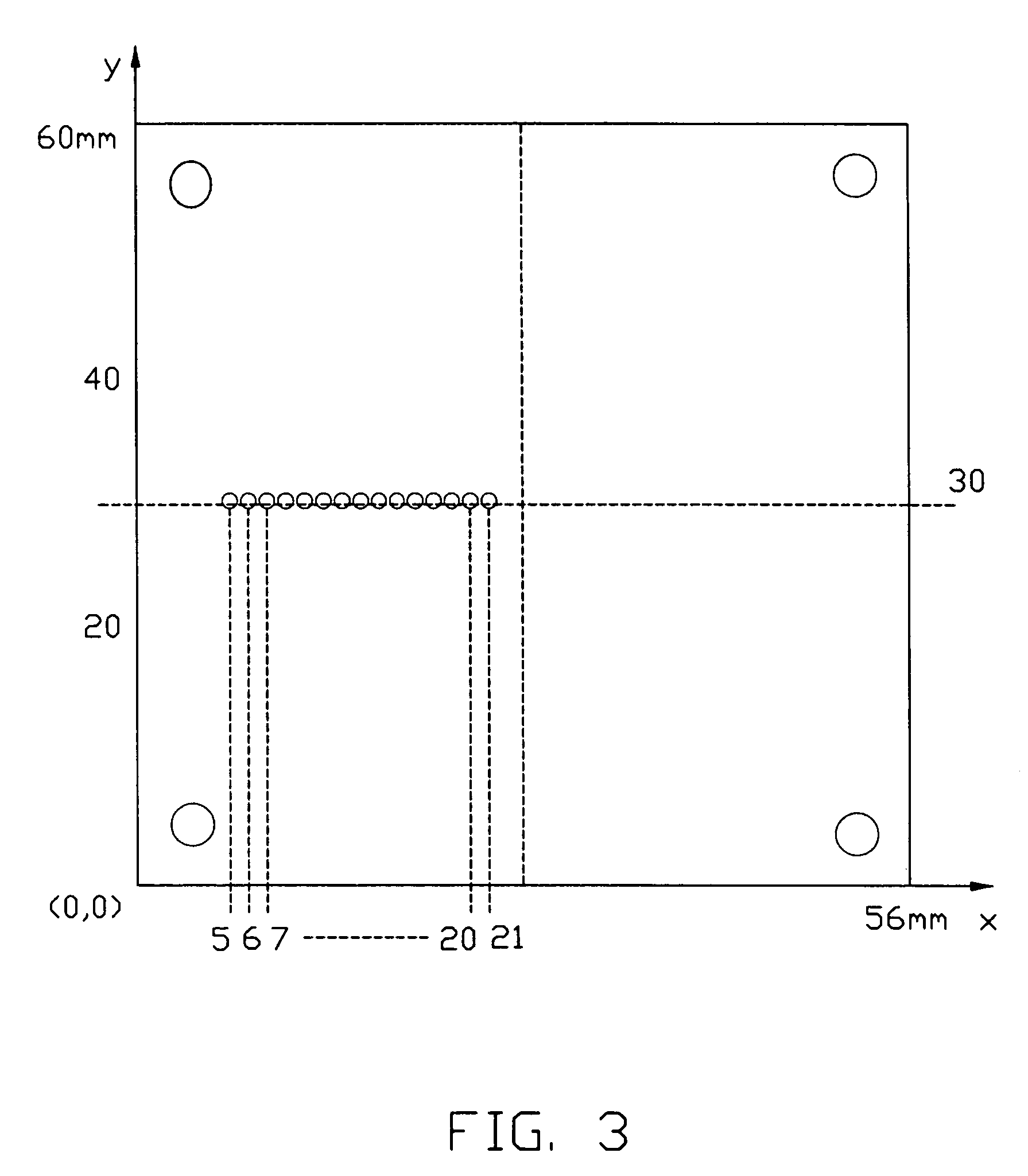
[0022] Each radiating patch defines a plurality of matching holes 202. The matching holes 202 are distributed on the left-half plane of the radiating patches and are located in a center line of the antenna width W. The matching holes 202 are of the same dimension. The diameter of each matchin...


PUM


Abstract

A high gain and omni-directive dual-patch antenna (1) for wireless communication under IEEE 802.11b / g standard includes a top and a bottom radiating patches (10) and (20) which have the same dimension, each of which in effect being a ground portion of the other, an air parch dielectric substrate between the two radiating patches, a feeding cable (30) inserted between the two radiating patches, and a support potion (40). A plurality of matching holes (202) is defined in both radiating patches and is provided for fast impedance match tuning and heat dissipation.

Description

BACKGROUND OF THE INVENTION [0001] 1. Field of the Invention [0002] The present invention relates generally to an antenna, and more particularly to a dual-patch antenna. [0003] 2. Description of the Prior Art [0004] In recent years, Wireless Local Area Network(WLAN) products under IEEE 802.11b / g standard, such as WLAN cards for computers are gaining popularity in wireless communication market. These cards benefit from high gain antennas. In many cases, patch antennas are used. [0005] As well known, a patch antenna usually utilizes a planar conductive patch disposed parallel to a big ground portion and separated from the ground portion by a thin dielectric layer. A feed point is provided to communicate electromagnetic energy to or from the patch. Antennas of this nature may be inexpensively manufactured and may be readily formed into low cost, light weighted phased antenna systems. A typical traditional patch antenna of this case is disclosed in U.S. Pat. No. 5,734,350. Though the tr...

Claims


Application Information

Patent Timeline
Patent Type & Authority Applications(United States)
IPC IPC(8): H01Q1/38H01Q9/04
CPCH01Q9/0442H01Q9/0407
Inventor HE, ZIMINGPENG, PINGZHAO, JIM X.TANG, CHIU-YUKAO, TIEN-LU
Owner HON HAI PRECISION IND CO LTD
Why Eureka
Try Eureka