Circuit, system and method for optical switch status monitoring

a technology of status monitoring and optical switch, applied in the field of optical or photonic switches, can solve the problem that none of the methods described enables monitoring of the switch path, and achieve the effect of facilitating the early detection of failures

Inactive Publication Date: 2005-07-07
LYNX PHOTONIC NETWORKS
View PDF98 Cites 13 Cited by
  • Summary
  • Abstract
  • Description
  • Claims
  • Application Information

AI Technical Summary

Benefits of technology

[0006] The present invention provides a circuit that is used to monitor, in real time, electrically addressable elements embedded in optical switches, particularly heaters embedded in thermo-optical switches. Monitoring of such elements facilitates the early detection of the failure of each such element, and thereby the failure of the switch as a whole. While the following description deals in detail with thermo-optical switches, the circuit, system and method disclosed herein can be implemented in all switch types that use an electronic control method for triggering the optical switching.

Problems solved by technology

None of the methods described enables monitoring of a switch path which is not currently passing light, i.e. one of the possible paths of a switch not passing light while the monitoring takes place.

Method used


Image

  • Circuit, system and method for optical switch status monitoring
  • Circuit, system and method for optical switch status monitoring
  • Circuit, system and method for optical switch status monitoring

Examples


Embodiment Construction

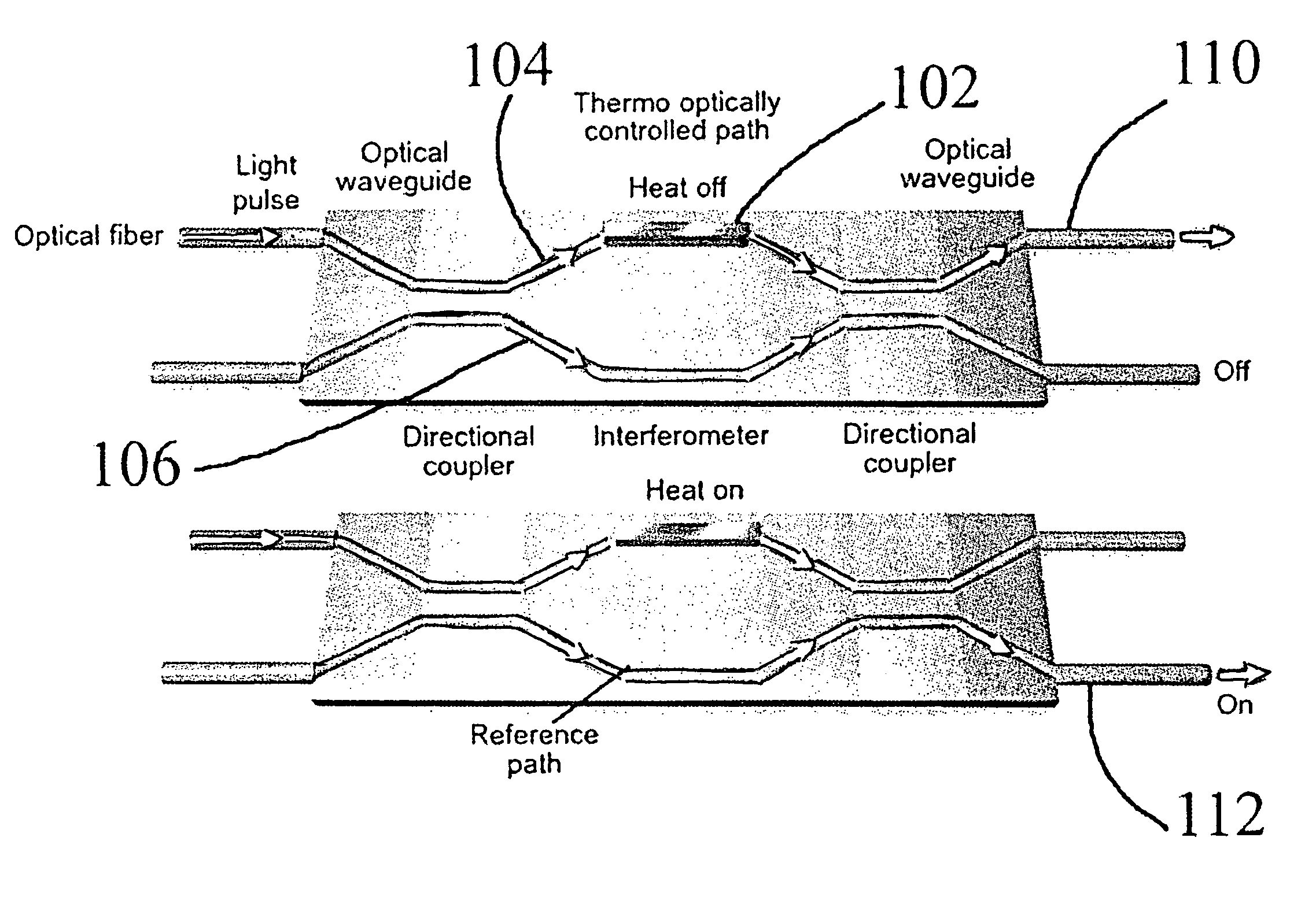
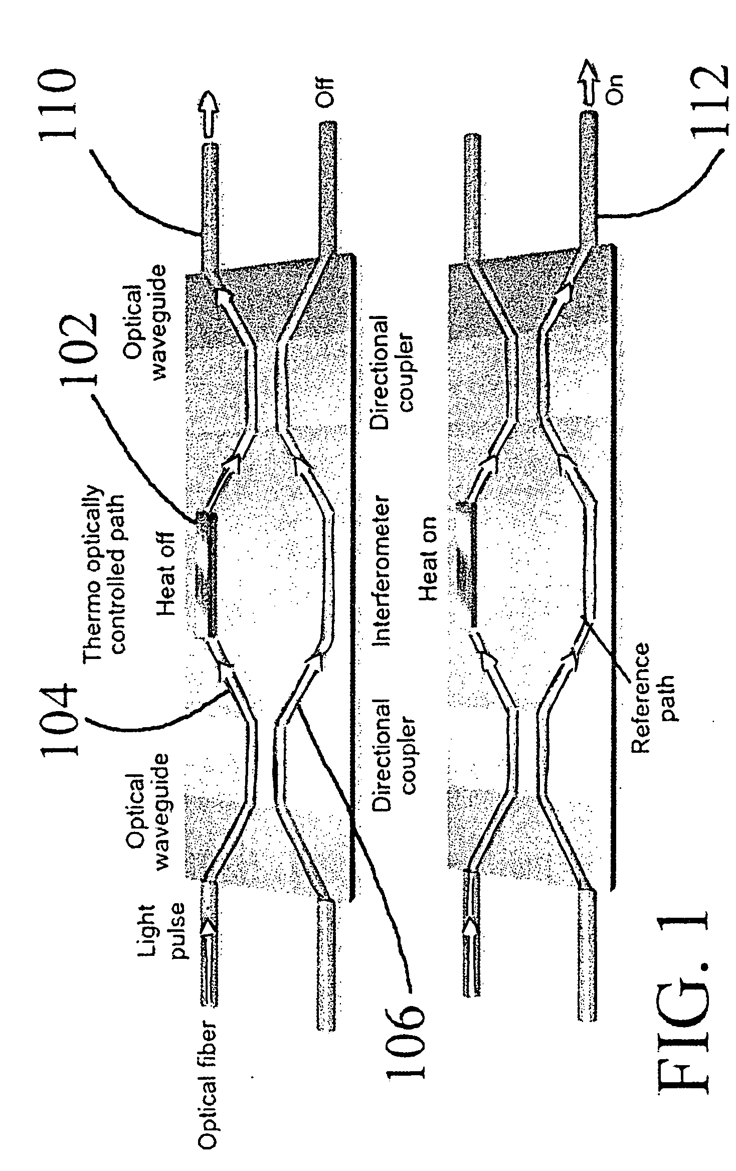
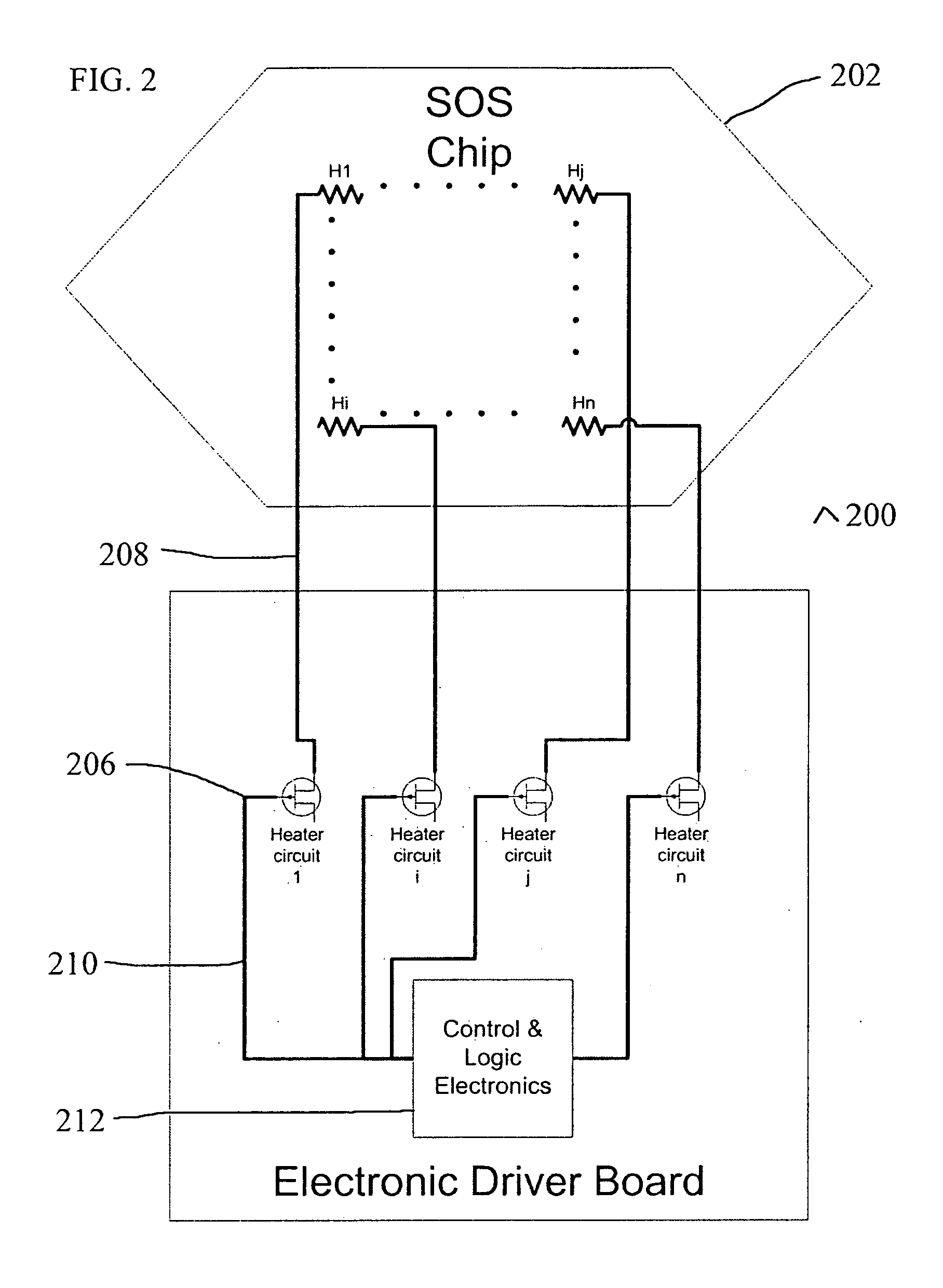
[0018] The present invention provides a monitoring circuit that is used to monitor electrically addressable elements embedded in optical switches. These elements are responsible for the optical switching action, for example through the electro-optic, thermo-optical effect or a mechanical actuation effect. The monitoring is based on electrical signals passed through an electrically addressable element such as a heater that is integral to the switch, the signal response monitored and evaluated. In other words, in contrast with prior art, the monitoring system and method disclosed herein provide electrical monitoring of the status of an optical switch. Furthermore, the method disclosed herein differs from prior art methods in that it monitors the actual switching mechanism, and not only the switching command and its processing, or the current switch position. The method also monitors all independent switching elements, verifying that they operate in all their positions needed to operat...


PUM

PropertyMeasurementUnit
voltageaaaaaaaaaa
electrically addressableaaaaaaaaaa
electrical testingaaaaaaaaaa

Abstract

A system and method for monitoring the status of an optical switch that includes at least one electrically addressable element operative to provide the switching action. The system comprises an electrical monitoring circuit operative to periodically test each such electrically addressable element while the switch is set to an ON, OFF or intermediate switching configuration, and a mechanism for effecting the periodic testing. The effecting mechanism may be for example a pulse width modulation algorithm. Optical monitoring that taps input and output optical fibers and checks pigtails may be added optionally to the electrical monitoring.

Description

FIELD AND BACKGROUND OF THE INVENTlON [0001] The present invention relates to optical or photonic switches, and in particular to the monitoring, preferably in real time, of the status of optical switches that include an electronic element that controls the switching actions. Such optical switches include, but are not limited to, a Mach Zehnder Interferometer (MZI) structure in which one or more heating elements are employed to affect the refractive characteristics of a waveguide, thereby enabling redirection of light passing through the optical or photonic switch. [0002] A network of such switches may be used to route an optical stream from a source to a destination on the network. It is imperative that each switch function properly, i.e. all its paths are in working order, and to facilitate this it is desirable to monitor all the switches (preferably in real time). The use of optical switches is well known in the communication arts. Network monitoring is also well known in the netw...

Claims


Application Information

Patent Timeline
Patent Type & Authority Applications(United States)
IPC IPC(8): G02F1/01G02F1/313G05B23/02
CPCG02F1/0121G02F1/3136G02F1/0147
Inventor KOPELOVITZ, BENILEVI, GILHARRIS, BERNARDWENDE, DAVIDRAPPAPORT, ELCHANANBERDUGO, YGAL
Owner LYNX PHOTONIC NETWORKS
Why Eureka
Try Eureka