Devices and methods for cooling microwave antennas

a microwave antenna and cooling device technology, applied in the field of microwave antennas, can solve the problems of unnecessarily ablating excess tissue, increasing the temperature of the feedline or shaft of the antenna, pain and other complications,

Active Publication Date: 2005-07-07
TYCO HEALTHCARE GRP LP
View PDF99 Cites 177 Cited by
  • Summary
  • Abstract
  • Description
  • Claims
  • Application Information

AI Technical Summary

Benefits of technology

[0008] One variation of an antenna cooling system may generally comprise a cooling handle assembly with an elongate outer jacket extending from the handle assembly and terminating at a tip which may be tapered. A microwave antenna may be positioned within the handle assembly and the outer jacket. An inflow tubing may extend into the handle body and distally into at least a portion of the outer jacket. A corresponding outflow tubing may also extend from within handle body such that the distal ends of the inflow tubing and the outflow tubing are in fluid communication with one another. A fluid may be pumped into the handle body via a pump through the inflow tubing such that the fluid comes into contact directly along a portion of the length, or a majority of the length, or the entire length of the antenna to allow for direct convective cooling of the antenna shaft. The fluid may exit the handle body through the outflow tubing. Thus, the cooling assembly is effective in cooling the antenna through direct contact rather than cooling the tissue surrounding the antenna, although the surrounding tissue may also be indirectly cooled through conduction via the assembly.
[0014] Another alternative may comprise integrated cooling lumens defined through the length of the sheath. Optional barriers may be defined through the length of sheath to divide the interior lumen into at least two separate volumes. Within these lumens, a first defined volume may hold a first chemical or liquid (e.g., water, saline, etc.) and a second defined volume may hold a second chemical or liquid (ammonium chloride, sodium nitrate, or potassium chloride, etc.). When a cooling effect is desired, the sheath may be flexed slightly such that the barriers are broken or fractured within the sheath and allows for the mixing between the chemicals to result in an endothermic reaction. Another alternative may include a slidable sheath assembly comprising an inner tube, which defines a first volume for holding a first chemical or liquid, and a concentric outer tube, which defines a second volume for holding a second chemical or liquid. Alternative variations may have the cooling sheath or tube integrated with or within the microwave antenna shaft.
[0016] Finally, yet another variation may include a microwave antenna in which the diameters of the inner conductor are modified so that proximal portions of the inner conductor functions as a heat sink to facilitate conductive cooling of the microwave antenna. This may be accomplished by creating an inner conductor having a larger proximal portion such that the proximal portion functions to draw and dissipate the heat at a faster rate.

Problems solved by technology

In minimally invasively treating diseased areas of tissue in a patient, trauma may be caused to the patient resulting in pain and other complications.
One cause of trauma may result from excess tissue being unnecessarily ablated by the microwave antenna assembly.
As the microwave antenna transmits microwave energy, the feedline or shaft of the antenna may increase in temperature and the contacting tissue may become charred or ablated unnecessarily.
Moreover, charred tissue may decrease the effectiveness of the microwave antenna.

Method used


Image

  • Devices and methods for cooling microwave antennas
  • Devices and methods for cooling microwave antennas
  • Devices and methods for cooling microwave antennas

Examples


Embodiment Construction

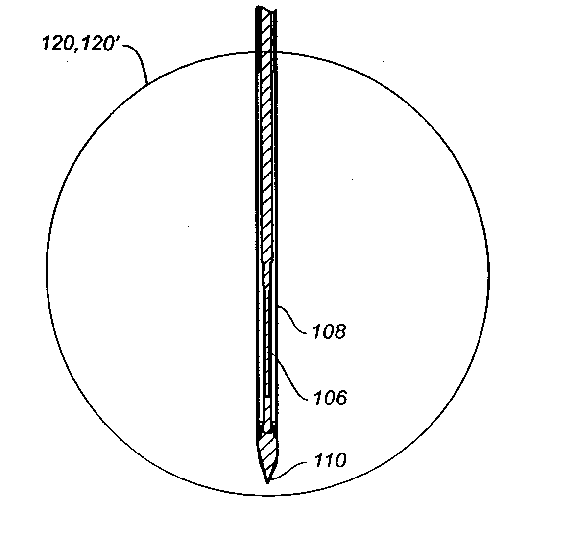
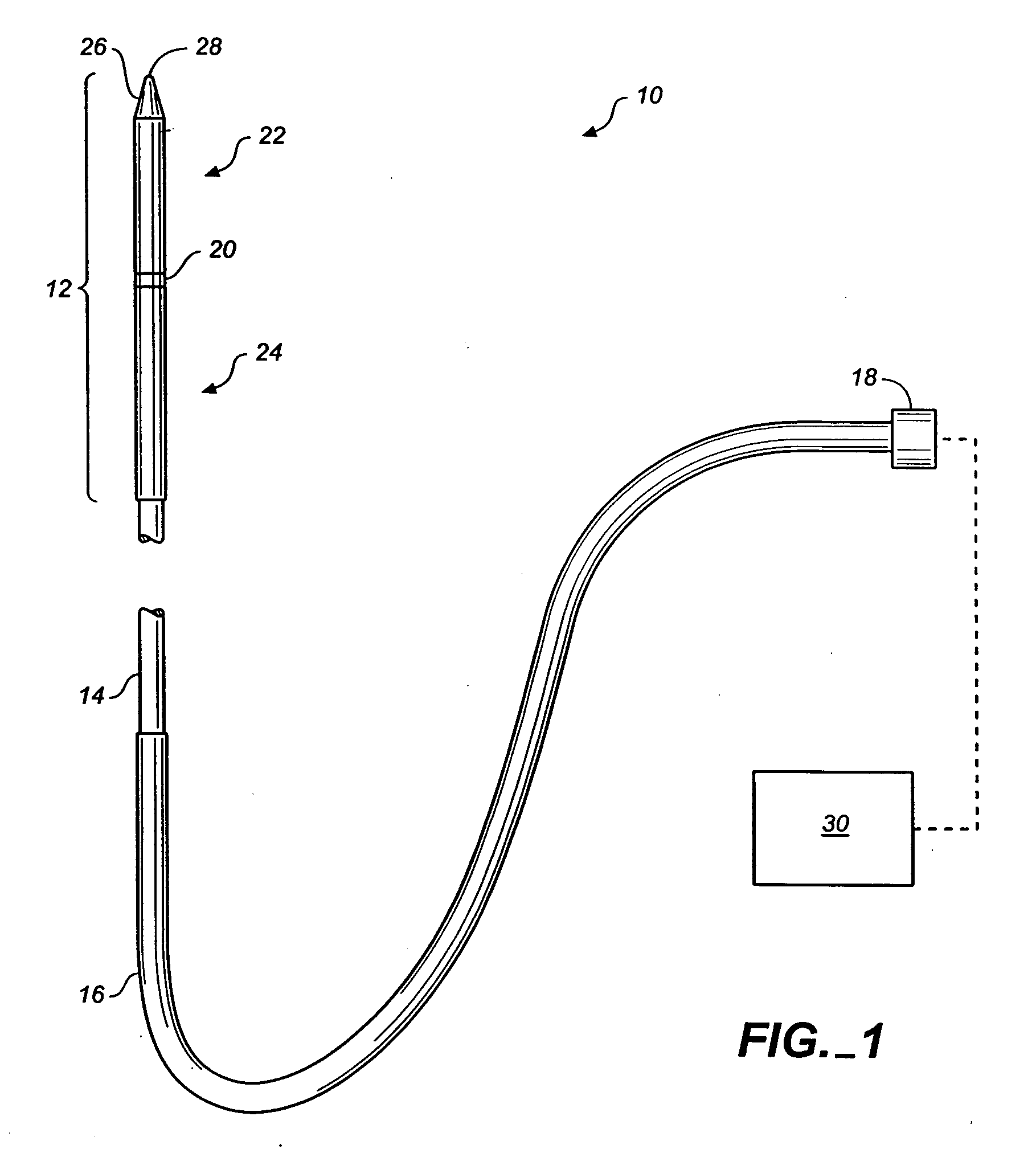
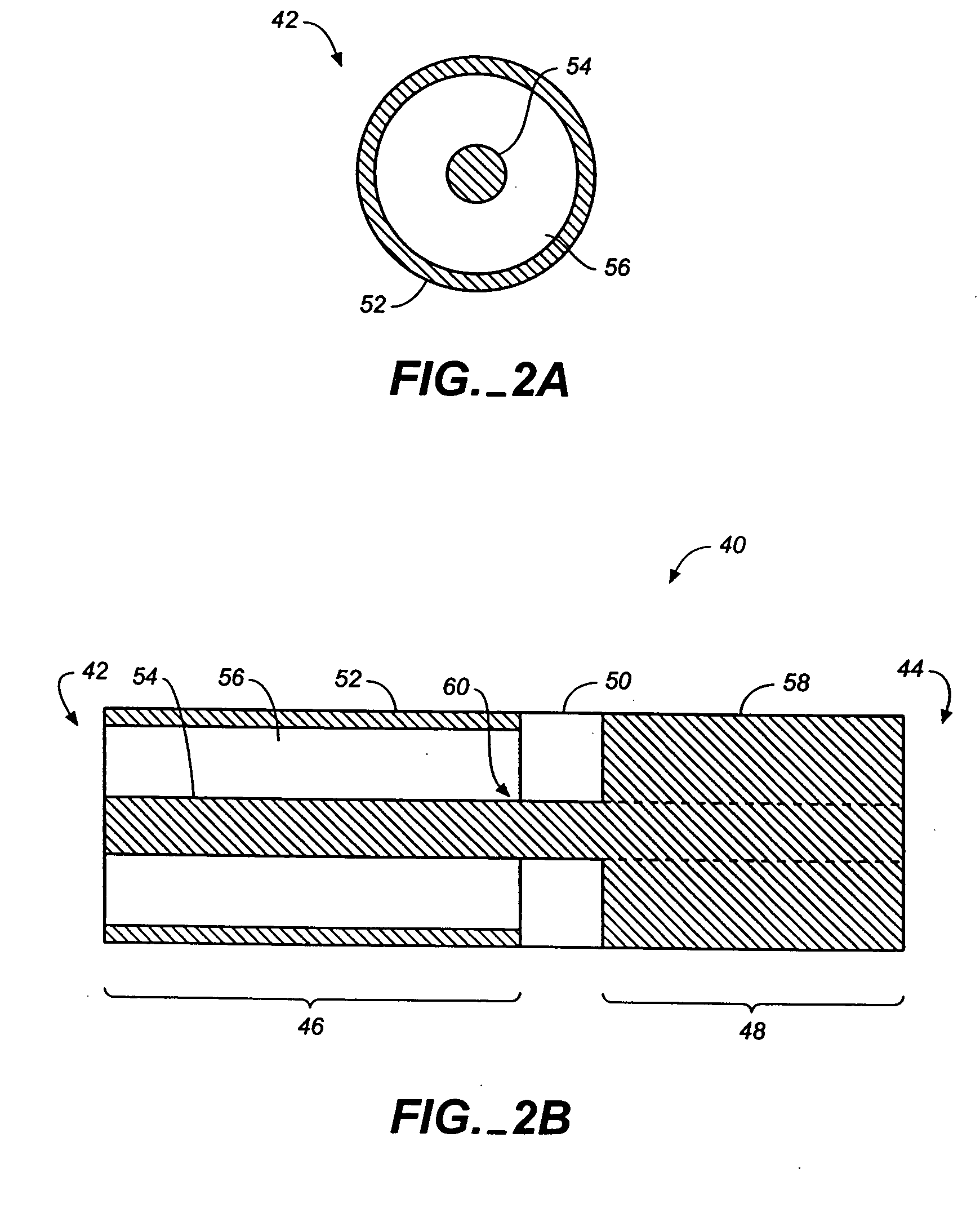
[0057] Various microwave antenna assemblies and cooling systems, as described herein, are less traumatic than devices currently available and as described in further detail below. Generally, in invasively treating diseased areas of tissue in a patient, trauma may be caused to the patient resulting in pain and other complications. One cause of trauma may result from excess tissue being unnecessarily ablated by the microwave antenna assembly. As the microwave antenna transmits microwave energy, the feedline or shaft of the antenna, as well as the radiation portion, may increase in temperature due to ohmic heating. Tissue in contact with a surface of the antenna may thus become charred or ablated unnecessarily. Aside from unnecessary trauma, charred tissue may decrease the effectiveness of the microwave antenna because of the changing impedance of the tissue as it dries out and becomes charred. The cooling systems, as described herein, may be used in conjunction with various types of m...


PUM


Abstract

Devices and methods for cooling microwave antennas are disclosed herein. The cooling systems can be used with various types of microwave antennas. One variation generally comprises a handle portion with an elongate outer jacket extending from the handle portion. A microwave antenna is positioned within the handle and outer jacket such that cooling fluid pumped into the handle comes into contact directly along a portion of the length, or a majority of the length, or the entire length of the antenna to allow for direct convective cooling. Other variations include cooling sheaths which form defined cooling channels around a portion of the antenna. Yet another variation includes passively-cooled systems which utilize expandable balloons to urge tissue away from the surface of the microwave antenna as well as cooling sheaths which are cooled through endothermic chemical reactions. Furthermore, the microwave antennas themselves can have cooling lumens integrated directly therethrough.

Description

FIELD OF THE INVENTION [0001] The invention relates generally to microwave antennas which may be used in tissue ablation applications. More particularly, the invention relates to devices and methods for reducing or maintaining temperatures of microwave antennas used in such applications. BACKGROUND OF THE INVENTION [0002] In the treatment of diseases such as cancer, certain types of cancer cells have been found to denature at elevated temperatures which are slightly lower than temperatures normally injurious to healthy cells. These types of treatments, known generally as hyperthermia therapy, typically utilize electromagnetic radiation to heat diseased cells to temperatures above 41° C. while maintaining adjacent healthy cells at lower temperatures where irreversible cell destruction will not occur. Other procedures utilizing electromagnetic radiation to heat tissue also include ablation and coagulation of the tissue. Such microwave ablation procedures, e.g., such as those performed...

Claims


Application Information

Patent Timeline
Patent Type & Authority Applications(United States)
IPC IPC(8): A61B18/00A61B18/18
CPCA61B18/18A61B18/1815A61N5/045A61B2018/00017A61B2018/00023A61B2017/00084
Inventor TUROVSKIY, ROMANKIM, STEVEN
Owner TYCO HEALTHCARE GRP LP
Why Eureka
Try Eureka