Switched resonant ultrasonic power amplifier system

a power amplifier and resonant technology, applied in the direction of mechanical vibration separation, contraceptive devices, therapy, etc., can solve the problems of variation in frequency, conventional power amplifier circuits that require a relatively large footprint, and are susceptible to drift and droop, so as to achieve significant reduction of random phase relationships

Active Publication Date: 2005-07-07
COVIDIEN AG
View PDF73 Cites 254 Cited by
  • Summary
  • Abstract
  • Description
  • Claims
  • Application Information

AI Technical Summary

Benefits of technology

[0010] The compensated clock signal is applied to an input of the compensated drive circuit. The compensated drive circuit includes a divider, a flip-flop, and a driver. A selected step-down ratio is applied to the compensated clock signal in the divider that results in a counter output signal delivered by the divider to the flip-flop, which has a lower frequency than the compensated clock signal. The counter output signal has a frequency that is approximately double the selected operating frequency for the ultrasonic transducer. A further reduction in frequency occurs as the counter output signal is applied to the flip-flop. The flip-flop generates two complementary square waves that are substantially 180° out-of-phase with respect to each other. Each of the square waves has a frequency that is at the selected operating frequency for the power amplifier and approximately one-half of the frequency of the counter output signal. These complementary square waves are applied to inputs of the driver for amplification and transmission to the inputs of the switched resonant power amplifier as driver output signals.
[0011] In another preferred embodiment, the driver includes a phase delay circuit that cooperates with the driver and provides phase compensation for the switched resonant power amplifier input signals. By controlling the phase relationship between the input signals, the driver is now phase correlated and random phase relationships are significantly minimized.
[0012] The switched resonant power amplifier includes a pair of insulated gate bi-polar transistors that receive the driver output signals. The insulated gate bi-polar transistors are biased such that when one is conducting the other one is not conducting, since one driver output signal has a value that corresponds to a “high” value, while the complementary driver output signal has a value that corresponds to a “low” value. When the driver signals change states (e.g., high to low and low to high), the respective insulated gate bi-polar transistors change from a conducting state to a non-conducting state, thereby providing an output to a primary side of an output transformer. On a secondary side of the output transformer is a pair of DC blocking output capacitors further coupled to an input of an ultrasonic device. The waveforms on the primary side of the output transformer are coupled across to a secondary side of the output transformer, where the waveforms combine to form the transducer driver signal. The ultrasonic device includes an ultrasonic transducer and a feedback transducer that are operatively coupled to the secondary side of the output transformer. The ultrasonic transducer receives the transducer drive signal from the output transformer and drives the transducer element to deliver the ultrasonic energy. The feedback transducer generates the feedback signal that is coupled to the wave shaping circuit.
[0013] In addition, the ultrasonic power amplifier system includes an output control circuit. The output control circuit includes the frequency generating and compensating circuit and the drive circuit. It cooperates with the wave shaping circuit for real time monitoring and control. The reset signal, that is representative of the feedback signal, is received by the frequency generating and compensating circuit for generating a compensated clock circuit. The divider reference signal is compared to the compensated reference signal in real time to control the compensated clock signal for frequency, phase, and / or gain. Additionally, the drive circuit includes a phase delay drive disposed in the driver for additional phase compensation between switched resonant power amplifier input signals. By providing real time monitoring and control of the drive signal to the ultrasonic device, the ultrasonic power amplifier system is capable of automatically monitoring and controlling the output of the ultrasonic device.

Problems solved by technology

Conventional power amplifier circuits for supplying drive signals to ultrasonic transducers are susceptible to drift and droop in power delivery and variations in frequency when the ultrasonic transducer is exposed to changing loading conditions.
Additionally, conventional power amplifier circuits require a relatively large footprint, are not lightweight, have efficiency problems, are generally complex circuits, and require heat sinking to dissipate heat generated during operation.
Due to their relatively large size and radiated heat, placement of conventional power amplifier circuits may be problematic in a medical treatment facility.

Method used


Image

  • Switched resonant ultrasonic power amplifier system
  • Switched resonant ultrasonic power amplifier system
  • Switched resonant ultrasonic power amplifier system

Examples


Embodiment Construction

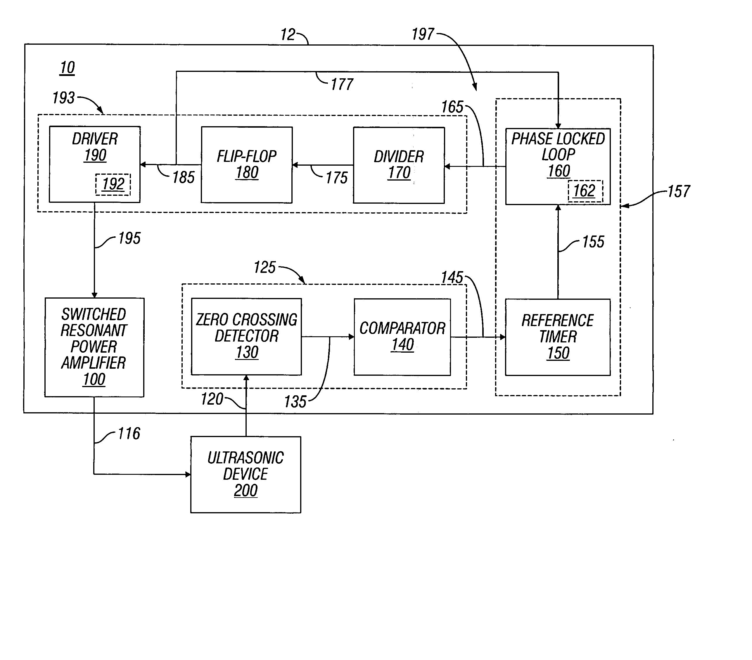
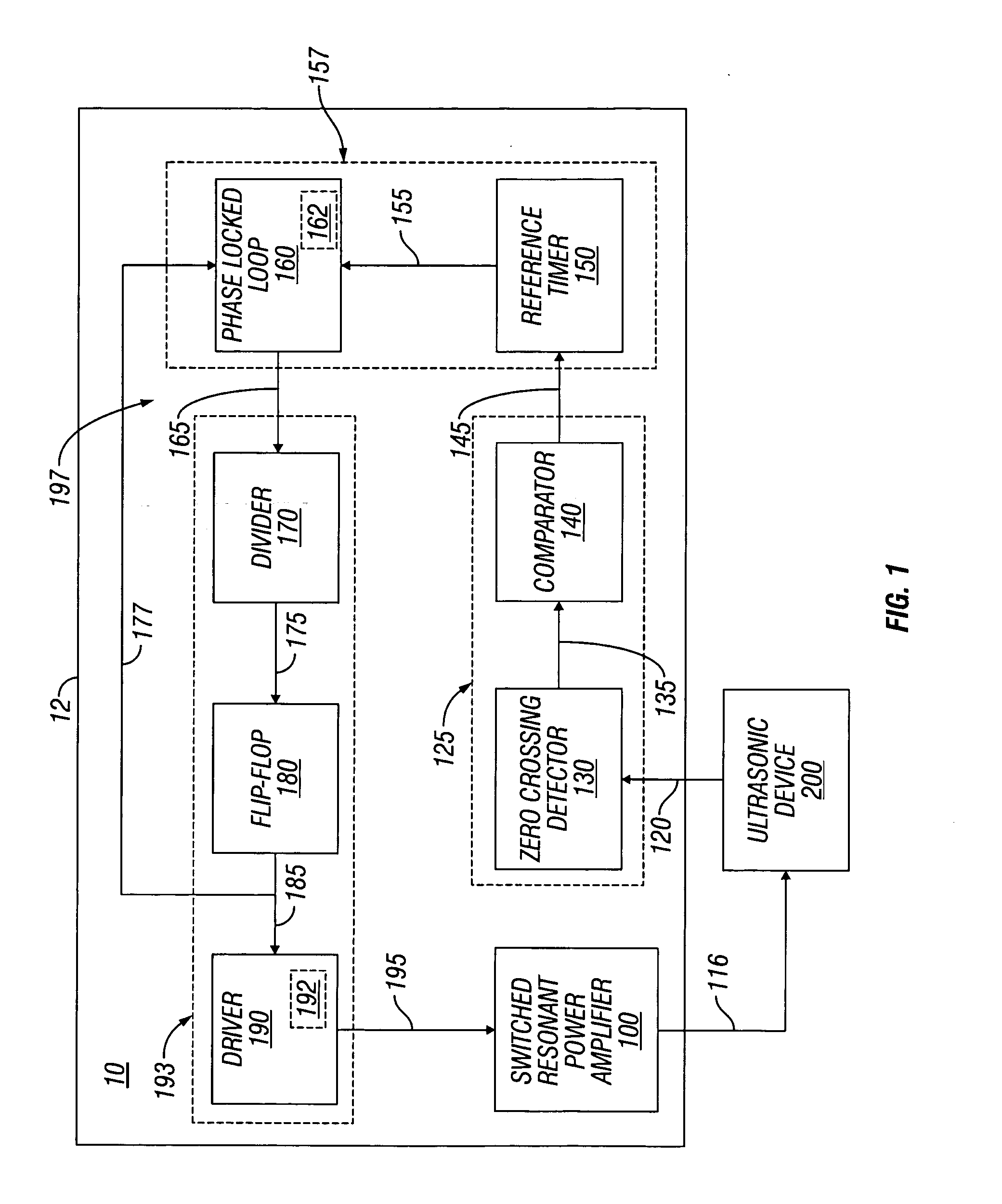
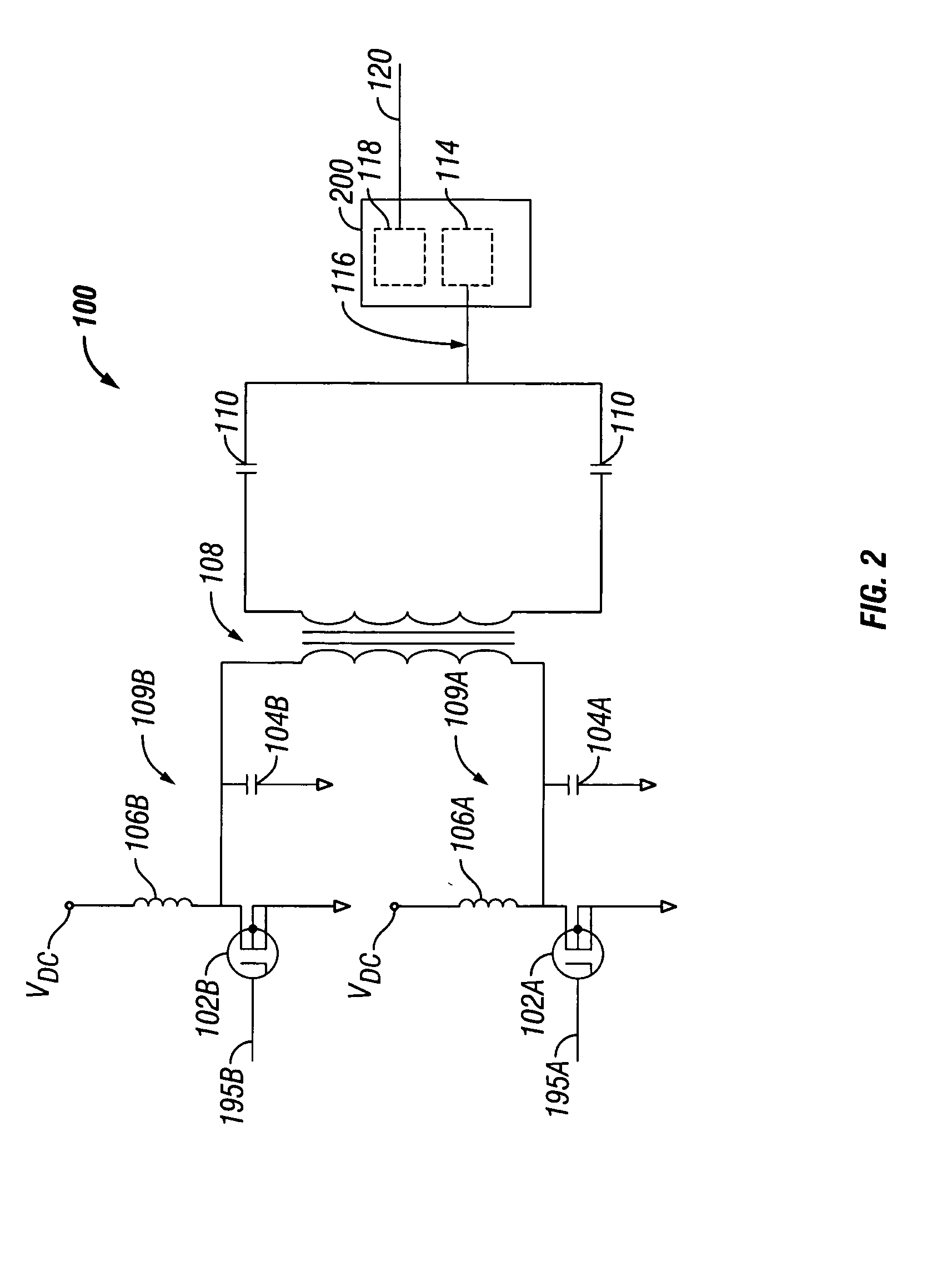
[0017] Embodiments of the presently disclosed switched resonant ultrasonic power amplifier system will now be described in detail with reference to the drawings, in which like reference numerals and characters designate identical or corresponding elements in each of the drawings.

[0018] As mentioned above, conventional power amplifier circuits, which supply drive signals to ultrasonic transducers, are typically susceptible to so-called “drift” and “droop” in power delivery and variations in frequency when the ultrasonic transducer is exposed to changing loading conditions. Moreover, conventional power amplifier circuits are typically very complex (e.g., complex circuitry), require a relatively large footprint and are quite burdensome, suffer from efficiency problems, and require a heat sink (or other cooling means) to dissipate heat generated during operation. As a result, placement of conventional power amplifier circuits may be problematic in a medical treatment facility.

[0019] R...


PUM


Abstract

A switched resonant power amplifier system for ultrasonic transducers is disclosed. The system includes an amplifier that receives and processes a driver output signal for generating a drive signal that is provided to an ultrasonic device for controlling output of the ultrasonic device. An output control circuit receives and processes a signal related to a feedback signal generated by the ultrasonic device and a divider reference signal, and generates a compensated clock signal that is adjusted for at least one of phase and frequency differences between the received feedback signal and the divider reference signal. A compensated drive circuit receives and processes the compensated clock signal for generating the divider reference signal, and for generating the driver output signal.

Description

CROSS REFERENCE TO RELATED APPLICATION [0001] This application claims the benefit of priority to U.S. Provisional Application Ser. No. 60 / 538,202 filed on Jan. 22, 2004, U.S. Provisional Application Ser. No. 60 / 527,812 filed on Dec. 8, 2003, and U.S. Provisional Application Ser. No. 60 / 515,826 filed on Oct. 30, 2003, the entire contents of which is being incorporated by reference herein.BACKGROUND OF THE INVENTION [0002] 1. Technical Field [0003] The present disclosure relates to devices for amplifying an input signal and providing an output signal to a surgical instrument. More particularly, the present disclosure relates to a switched resonant ultrasonic power amplifier system for surgical instruments. [0004] 2. Background of Related Art [0005] Conventional power amplifier circuits for supplying drive signals to ultrasonic transducers are susceptible to drift and droop in power delivery and variations in frequency when the ultrasonic transducer is exposed to changing loading condi...

Claims


Application Information

Patent Timeline
Patent Type & Authority Applications(United States)
IPC IPC(8): A61F7/00A61B18/00B06B1/02H03F1/02H03F3/217
CPCB06B1/0253A61N7/00B06B2201/76B06B1/0261H10N30/802A61N2007/0056
Inventor ORSZULAK, JAMES H.MCPHERSON, JAMES W.
Owner COVIDIEN AG
Why Eureka
Try Eureka