Apparatus for driving optical head

Inactive Publication Date: 2005-07-07
TRANSPACIFIC OPTICS
View PDF9 Cites 11 Cited by
  • Summary
  • Abstract
  • Description
  • Claims
  • Application Information

AI Technical Summary

Benefits of technology

[0009] While there is incompetence in the conventional arts stated in the background of invention above, one of the goals of the present invention is to use a set of springs to compensate the tolerance of the transmission gea

Problems solved by technology

There is a problem coming along with this change, the precision accuracy.
Due to the high requirement of precision accuracy, a severe tolerance limit is important for the sled mechanism of the optical pickup head, especially when the sled mechanism itself is also getting smaller and slimmer along with the drives.
As we can see in the FIG. 1, although the idea of the design is simple, the mass production yield rate is low when there is a severe tolerance limit.
When a

Method used


Image

  • Apparatus for driving optical head
  • Apparatus for driving optical head
  • Apparatus for driving optical head

Examples


Embodiment Construction

[0026] The following is a description of the present invention. However, other than the detailed description, the present can also be widely implemented in other embodiment, and the scope of the present invention is not limited and is based on the future patent scope.

[0027] Moreover, to provide more detailed description and clearer understanding of the present invention, the figures are not drawn according to the corresponding scale. Some measurement and scale have been exaggerated and some unrelated details are not drawn to make figure concise.

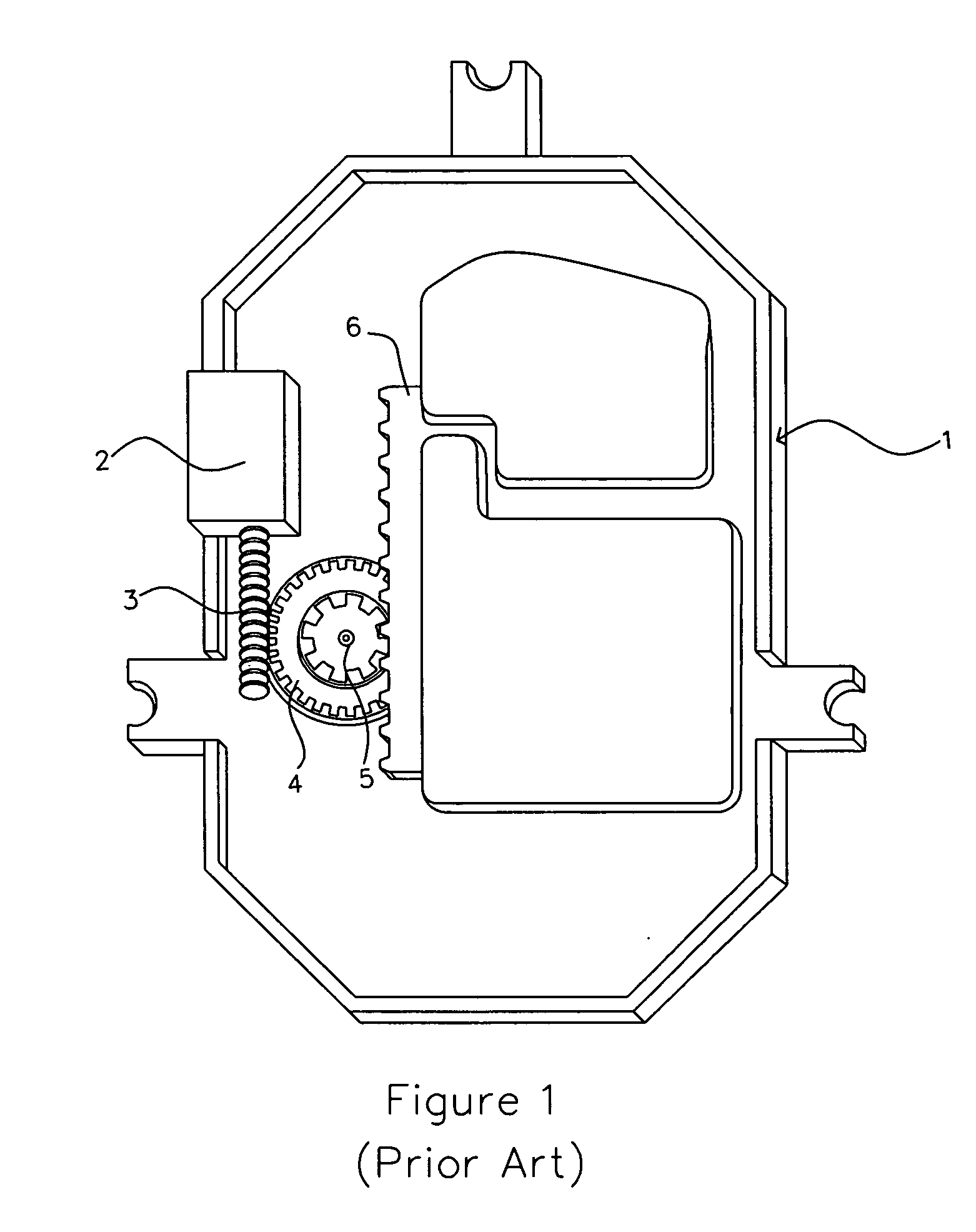
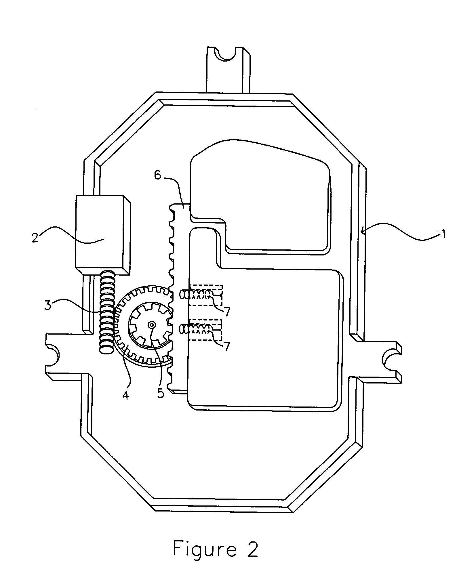
[0028] The present invention is illustrated in FIG. 2, the present invention comprises a drive 1, a drive motor 2, a worm 3 which is driven by the drive motor, a worm wheel 4 which is engaged with the worm 3 and driven by it, a spur gear 5 which is attached to the worm wheel 4 and rotate simultaneously with it, a rack 6 which is engaged with the spur gear and move forward and backward while the spur gear is rotating counterclockwise and clo...


PUM


Abstract

The present invention discloses a sled mechanism for the optical pick-up head, which utilized a drive motor to drive a worm to make a worm wheel rotate. After driven by the worm, the worm wheel will drive a spur gear, which is engaged with a rack and drive the rack forward and backward, and then move the optical pickup head attached to the rack to the right position. In the meanwhile, a set of spring unit is utilized to compensate the tolerance of the components of the gear set.

Description

BACKGROUND OF THE INVENTION [0001] 1. Field of the Invention [0002] The present invention relates to a sled mechanism, which utilizes a set of springs near the optical pickup head. With this set of springs attached to the rack where the pickup head is, the rack and the gear set driven by drive motor can be engaged with each other more tightly. As a result, the tolerance limit can be higher because this design can compensate part of the tolerance. Moreover, the present invention can also improve the yield rate of the mass production, because the slim spindle of disc drive needs high precision accuracy and the present invention is to compensate part of the tolerance. To sum up, the present invention can increase the tolerance, make the drive motor drive the pickup head more smoothly, and improve the mass production yield, by utilizing a set of springs attached to the rack. [0003] 2. Background Description [0004] With the progress of high technology and the advancement of optical stora...

Claims


Application Information

Patent Timeline
IPC IPC(8): G11B7/08G11B7/085G11B7/09
CPCG11B7/08582
Inventor PU, HSIN-MING
Owner TRANSPACIFIC OPTICS
Why Eureka
Try Eureka