
System and method for validating radio frequency identification tags

a radio frequency identification and validation system technology, applied in the field of radio frequency identification tags, can solve the problems of inability to discriminate between labels with a long read range, inability to guarantee the readability of all tag inlays that they ship, and no known commercially available system

Inactive Publication Date: 2005-07-14
GEORGE SCHMITT & CO
View PDF2 Cites 58 Cited by
  • Summary
  • Abstract
  • Description
  • Claims
  • Application Information

AI Technical Summary

Benefits of technology

[0008] Accordingly, it is an object of the present invention to provide a system and method for validating radio frequency identification tags to ensure proper functioning thereof which is capable of ensuring that 100% (or at least very close to 100%) of the RFID labels are readable.
[0011] Still another object of the present invention is to provide a system and method for validating radio frequency identification tags to ensure proper functioning thereof having the above characteristics and which is capable of reading and validating labels moving at a relatively fast speed.

Problems solved by technology

Currently, RFID tag manufacturers are not able to guarantee that all tag inlays that they ship are readable, functional tags—in fact, as many as 20% of the incoming tags may be non-readable.
The difficulty is in discriminating between labels that have a long read range, but that are spaced closely together.
There is no known commercially available system which will effectively guarantee that substantially 100% of the ultra high frequency (e.g., 900 MHz) tags mounted in a roll at close proximity (e.g., a few inches apart) and that have a long read range (e.g., greater than 24″) are all functional tags, while being processed at normal production speeds (e.g., several hundred labels per minute).

Method used


Image

  • System and method for validating radio frequency identification tags
  • System and method for validating radio frequency identification tags
  • System and method for validating radio frequency identification tags

Examples


Embodiment Construction

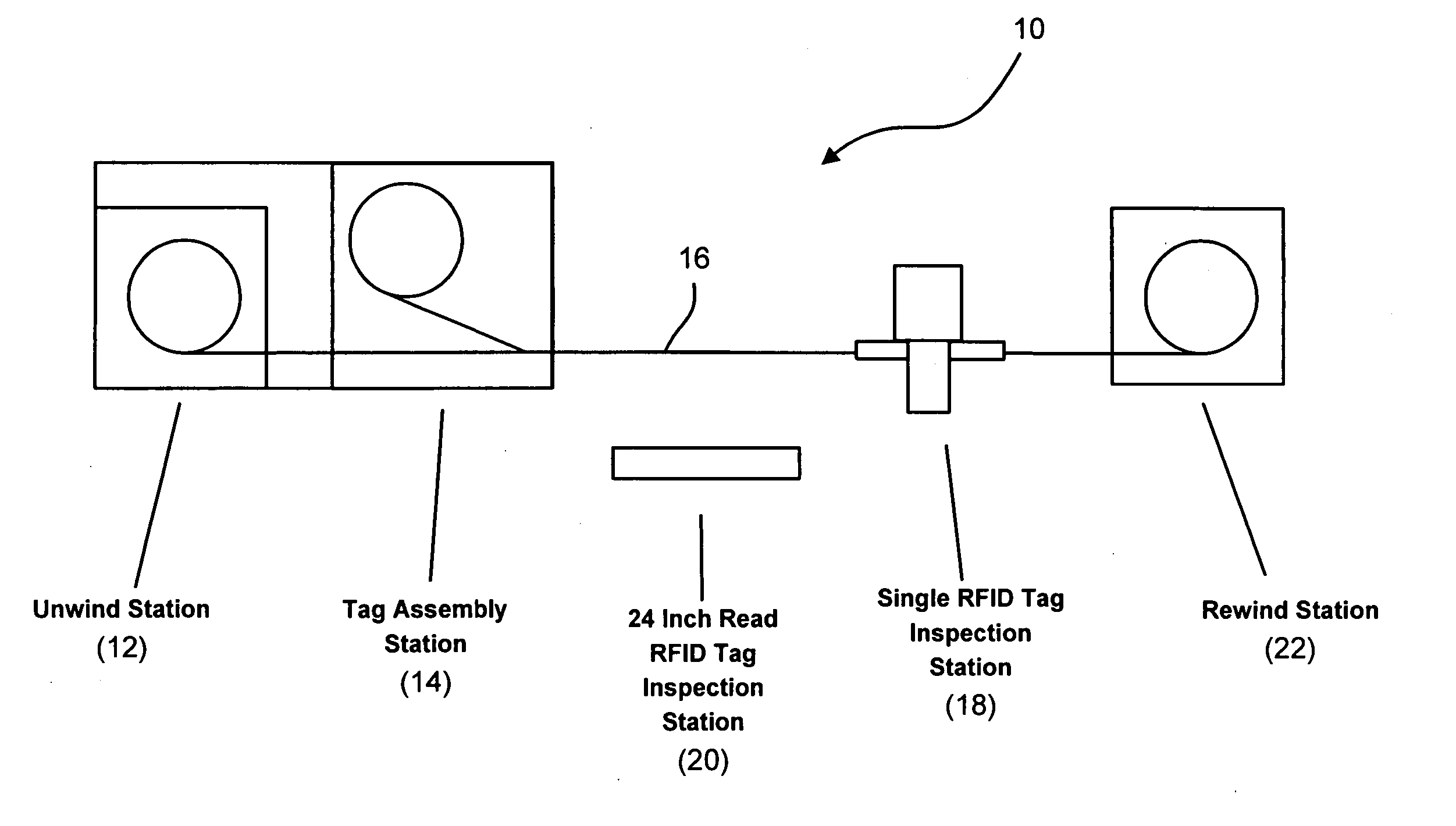
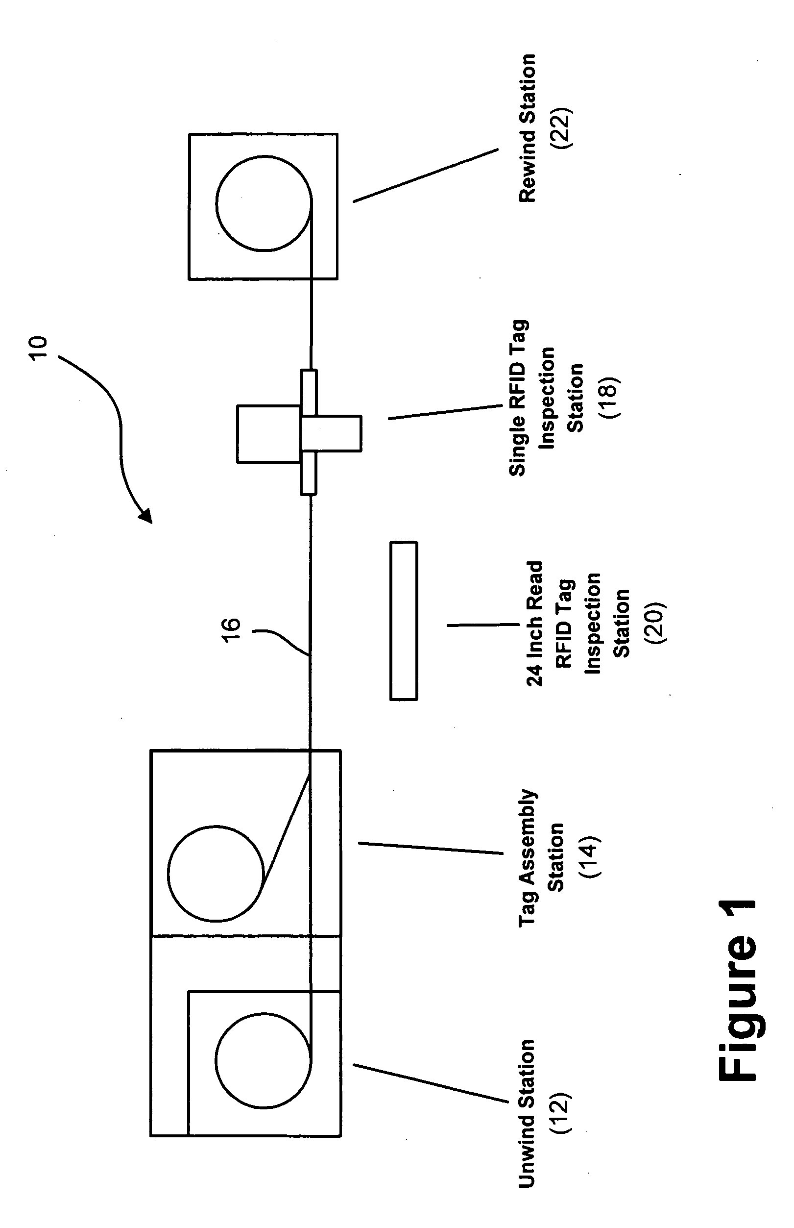
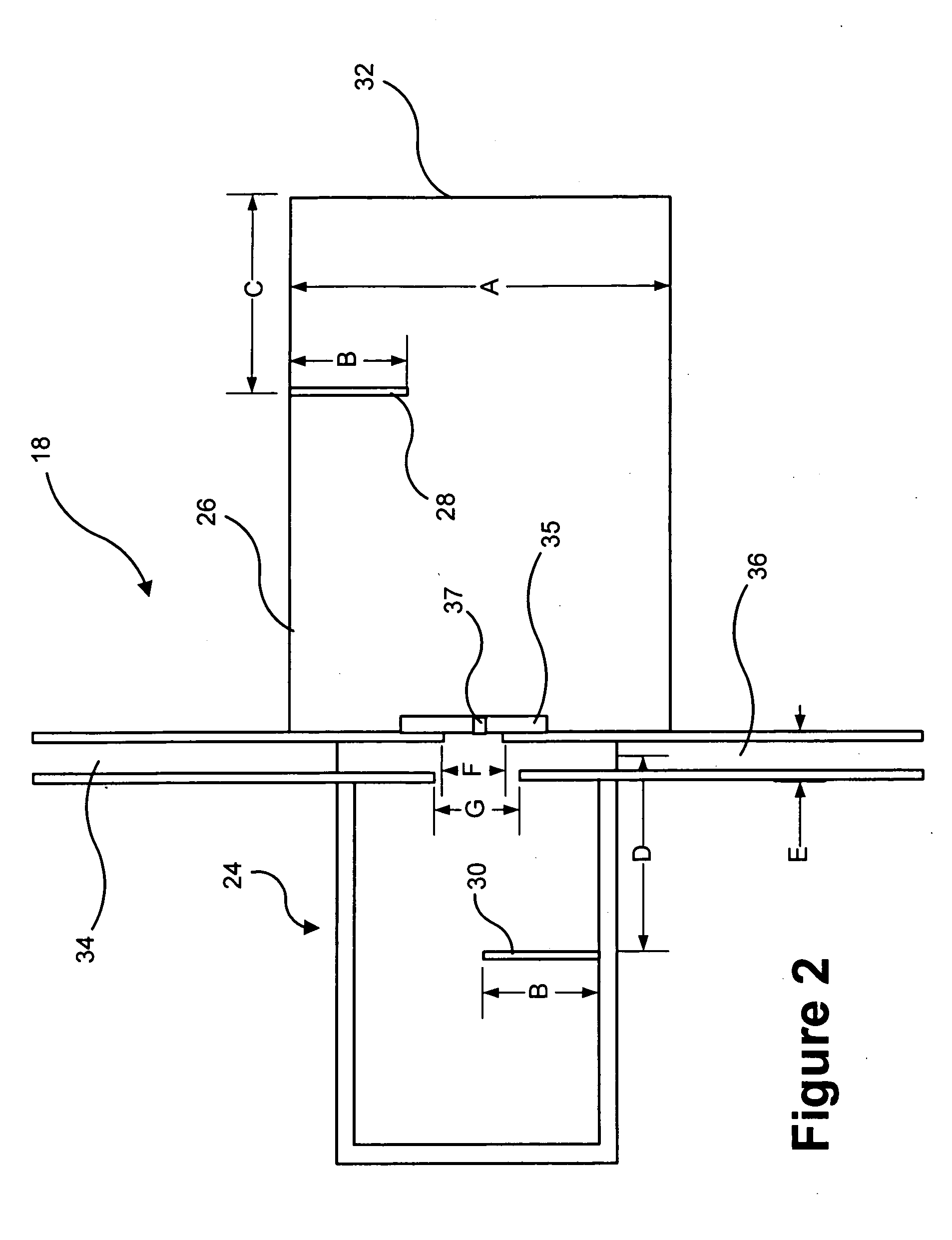
[0034] As discussed in more detail above, existing systems for reading RFID tags are optimized to read many tags at the same time. These RFID tags have typical rates of failure to read of about 20%. Existing systems do not permit the verification of a single tag, activating the single RFID tag and no others. As an example, the ultra high frequency 900 MHz tags use a spread of frequencies from about 902 MHz through about 928 MHz. The RFID reader produces a transmitted pulse of sufficient power to energize and activate any illuminated RFID tags. The RFID reader then goes into a receive state to receive any transmissions from the activated RFID tags.

[0035] However, a problem exists in that adjacent tags on the strip can be energized and activated, making it difficult to know exactly which particular tag of a group of tags is responding. The present invention allows the speedy and automated verification of individual tags when it is not known beforehand that the tag is operational. The...


PUM

PropertyMeasurementUnit
distanceaaaaaaaaaa
frequenciesaaaaaaaaaa
frequencyaaaaaaaaaa

Abstract

A system for validating each of a plurality of radio frequency identification tags disposed on a web in close proximity to one another to ensure proper functioning thereof includes a narrow angle radio frequency identification tag reading station which reads a designation of each radio frequency identification tag individually in order to generate a first list of tag designations read thereby and a wide angle radio frequency identification tag reading station which reads designations of a plurality of radio frequency identification tags simultaneously from a long range in order to generate a second list of tag designations read thereby. The system also includes a processor which compares the first list of tag designations with the second list of tag designations and evaluates the functionality of the plurality of radio frequency identification tags based at least in part upon the comparison.

Description

RELATED APPLICATIONS [0001] This patent application claims the benefit of, under Title 35, United States Code, Section 119(e), U.S. Provisional Patent Application No. 60 / 536,097, filed Jan. 13, 2004 and U.S. Provisional Patent Application No. 60 / 591,397, filed Jul. 27, 2004.FIELD OF THE INVENTION [0002] The present invention relates generally to radio frequency identification tags, used for example in connection with warehousing, inventory management and product tracking, and more particularly to systems and methods for validating such radio frequency identification tags to ensure proper functioning thereof. BACKGROUND OF THE INVENTION [0003] Radio frequency identification (RFID) is a technology which is rapidly gaining acceptance in a variety of fields including warehousing, inventory management, and product tracking. It is based on a system which is comprised of a reader (e.g., a radio transmitter / receiver with antennae), a tag (comprised of a miniature antenna with a silicone chi...

Claims


Application Information

Patent Timeline
Patent Type & Authority Applications(United States)
IPC IPC(8): G01R31/28G06K19/077
CPCG01R31/2822G06K7/0095Y10T29/49004G06K19/07749G06K19/07718
Inventor BOSCO, EDWARD MICHAELGUNTHER, WILLIAM G.GOLICZ, ROMANGOLICZ, STEFAN G.
Owner GEORGE SCHMITT & CO
Learn More