Heat source unit of air conditioner and air conditioner

a heat source unit and air conditioner technology, applied in lighting and heating apparatus, refrigeration machines, compression machines with reversible cycles, etc., can solve the problem that the heat source unit of a conventional simultaneous cooling and heating device cannot be used as the heat source unit for the switchable cooling and heating devi

Inactive Publication Date: 2005-07-14
DAIKIN IND LTD
View PDF1 Cites 16 Cited by
  • Summary
  • Abstract
  • Description
  • Claims
  • Application Information

AI Technical Summary

Benefits of technology

[0011] However, in the heat source unit of the air conditioner of the present invention, the auxiliary heat exchanger conventionally used only as the condenser is used as the evaporator. Specifically, it is constituted so that a second switching means is provided, which can switch so that the auxiliary heat exchanger functions as an evaporator or a condenser. Consequently, in this heat source unit, there is no need to perform the operation of supplying the discharged refrigerant gas of the compressing means to the first refrigerant gas piping while actuating the main heat exchanger as the condenser, as in the conventional heat source unit for a simultaneous cooling and heating device, and the load of the heat source unit can be regulated by actuating the main heat exchanger as the condenser and actuating the auxiliary heat exchanger as the evaporator. Consequently, there is no need in this heat source unit for the check valve of the first refrigerant gas piping and the delivery piping provided in a conventional heat source unit.
[0023] consequently, the water can flow in each heat exchanger from above to below. Thereby, it becomes difficult for corrosive components and the like contained in the water to stagnate inside the heat exchanger, and scaling can be suppressed.

Problems solved by technology

Consequently, because the first refrigerant gas piping cannot be used as the refrigerant gas piping for the switchable cooling and heating device, the heat source unit for a conventional simultaneous cooling and heating device cannot be used as the heat source unit for the switchable cooling and heating device.

Method used


Image

  • Heat source unit of air conditioner and air conditioner
  • Heat source unit of air conditioner and air conditioner
  • Heat source unit of air conditioner and air conditioner

Examples


first embodiment

[0034] The following explains the first embodiment of the present invention, based on the drawings.

[0035] (1) Constitution of the Air Conditioner

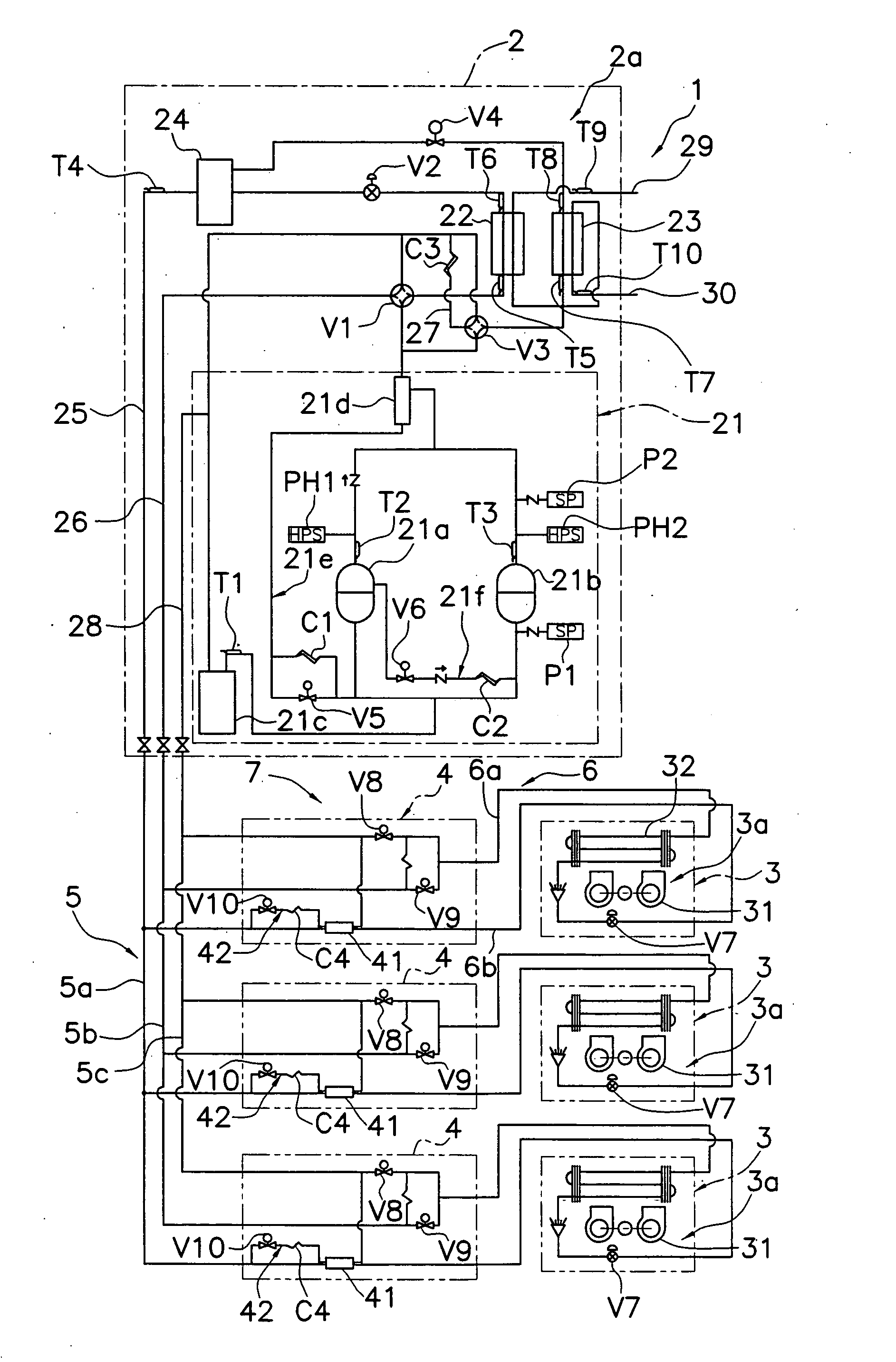
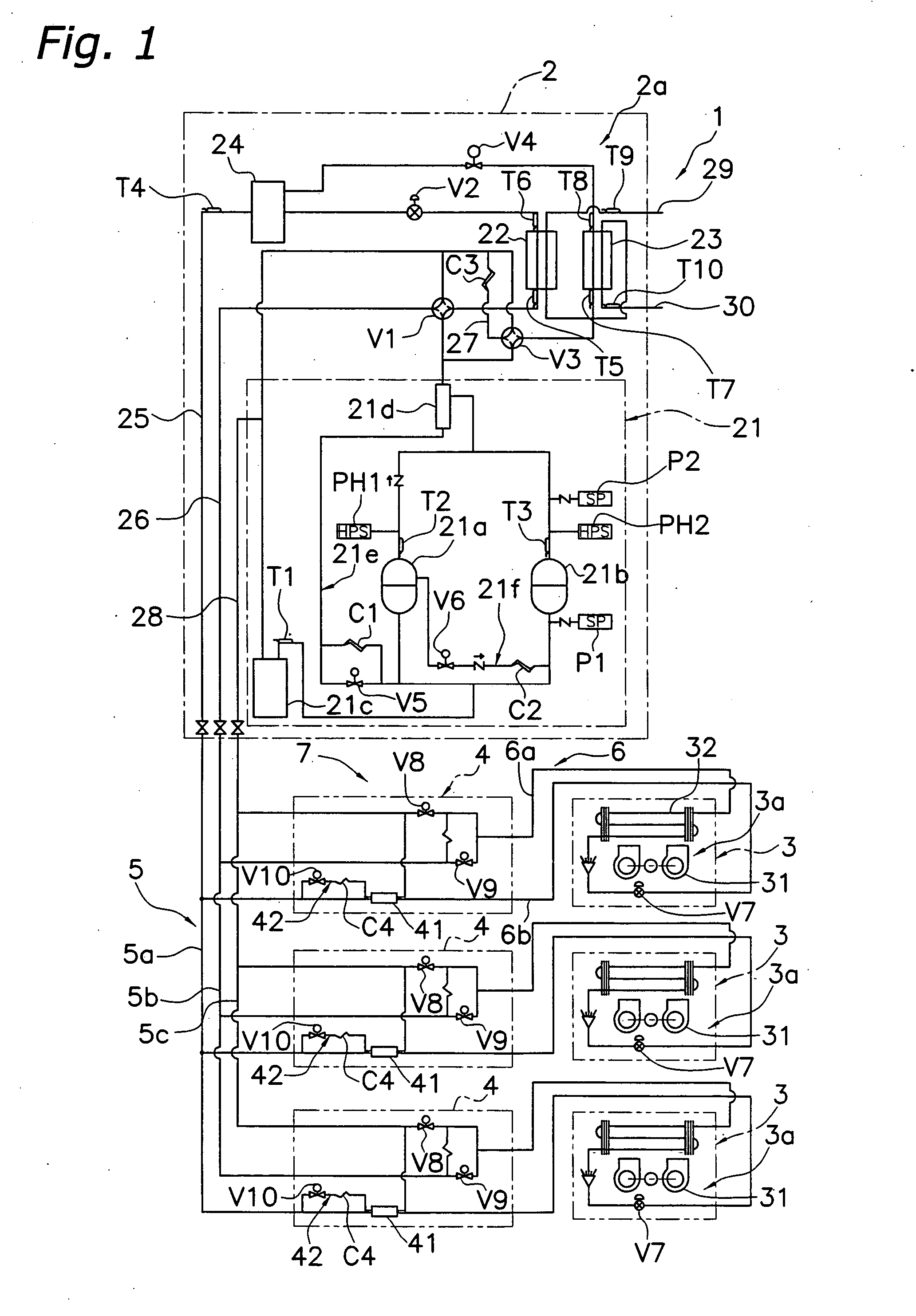
[0036]FIG. 1 is a refrigerant circuit diagram of an air conditioner 1 according to the first embodiment of the present invention.

[0037] The air conditioner 1 is capable of simultaneous cooling and heating operation, and includes one heat source unit 2, a plurality (three units in the present embodiment) of utilization units 3, a connecting unit 4 provided for each utilization unit 3, a first connecting piping bank 5 that connects the heat source unit 2 and the connecting units 4, and a second connecting piping bank 6 that connects the connecting units 4 and the utilization units 3.

[0038] {circle over (1)} Heat Source Unit

[0039] The heat source unit 2 uses water as the heat source, and principally includes a compressing means 21, a main heat exchanger 22, a first switching means V1, a main refrigerant switching means V2, an auxiliary he...

second embodiment

[0090]FIG. 7 is a view that depicts the main components of the refrigerant circuit of an air conditioner 101 according to the second embodiment of the present invention.

[0091] The basic constitution of the air conditioner 101 is the same as the air conditioner 1 of the first embodiment, with a difference only in that the solenoid valve employed as the auxiliary refrigerant switching means V4 in the first embodiment is changed to the motor operated expansion valve capable of controlling the refrigerant flow. Thereby, the air conditioner 101 of the present embodiment has features the same as those of the air conditioner 1 of the first embodiment, and also has the following features.

[0092] Because the air conditioner 101 of the present embodiment employs a motor operated expansion valve capable of controlling the refrigerant flow in an auxiliary refrigerant switching means V104 of a heat source side refrigerant circuit 102a, the amount of evaporation and amount of condensation of the...

third embodiment

[0093]FIG. 8 is a view that depicts the main components of the refrigerant circuit of an air conditioner 201 according to the third embodiment of the present invention.

[0094] The air conditioner 201 uses the heat source unit 2 for the simultaneous cooling and heating device of the first embodiment as the heat source unit for the switchable cooling and heating device. Herein, the constitution of the heat source unit 2 and the utilization units 3 is the same as that of the first embodiment. In addition, the connecting units 4 for the simultaneous cooling and heating device are eliminated. Further, the first refrigerant gas piping 26 of the heat source unit 2 and the utilization side heat exchangers 32 of the utilization units 3 are connected via a connecting refrigerant circuit 207, and the refrigerant liquid piping 25 of the heat source unit 2 and the utilization side expanding means V7 of the utilization units 3 are connected via the connecting refrigerant circuit 207. Herein, the ...


PUM


Abstract

The present invention provides a heat source unit capable of being used in either an air conditioner for switchable cooling and heating operation or an air conditioner for simultaneous cooling and heating operation. An air conditioner principally includes one heat source unit, a plurality of utilization units, and a connecting unit provided for each utilization unit. The heat source unit uses water as the heat source, and principally includes a compressing means, a main heat exchanger, a first switching means, a main refrigerant switching means, an auxiliary heat exchanger connected in parallel with the main heat exchanger, a second switching means, an auxiliary refrigerant switching means, and a liquid receiver. The auxiliary heat exchanger is capable of switching between functioning as an evaporator and a condenser, by the second switching means.

Description

FIELD OF THE INVENTION [0001] The present invention relates to an air conditioner heat source unit and an air conditioner, and more particularly relates to an air conditioner heat source unit including a heat source side refrigerant circuit connected to a plurality of utilization side refrigerant circuits via a connecting refrigerant circuit, and to an air conditioner. RELATED ART [0002] Conventional air conditioners are known that are capable of switchable cooling and heating operation or simultaneous cooling and heating operation, and include a plurality of utilization units, and a heat source unit. Each utilization unit includes a utilization side refrigerant circuit that includes a utilization side heat exchanger and a utilization side expanding means. The heat source unit includes a heat source side refrigerant circuit that includes a compressing means that compresses a refrigerant, a main heat exchanger, a first switching means for making the main heat exchanger to function as...

Claims


Application Information

Patent Timeline
Patent Type & Authority Applications(United States)
IPC IPC(8): F25B13/00
CPCF25B13/00F25B2313/004F25B2313/007F25B2313/021F25B2313/0215F25B2400/075F25B2313/02323F25B2313/0233F25B2313/02331F25B2313/02334F25B2313/0231F25B2400/13
Inventor MATSUOKA, SHINYASADA, SHINRIINOUE, HIROYUKIFUCHIKAMI, HIROSHIUMEDA, ATSUSHI
Owner DAIKIN IND LTD
Why Eureka
Try Eureka