Extended impingement cooling device and method

a cooling device and extended impingement technology, applied in the direction of machines/engines, laminated elements, light and heating equipment, etc., can solve the problem that certain areas of these liners cannot be adequately cool

Active Publication Date: 2005-07-14
RTX CORP
View PDF16 Cites 56 Cited by
  • Summary
  • Abstract
  • Description
  • Claims
  • Application Information

AI Technical Summary

Problems solved by technology

Certain areas of these liners cannot be adequately cool by impingement air flow because the air supply plenum is blocked by other equipment or structures located in proximity to the impingement sheet.

Method used


Image

  • Extended impingement cooling device and method
  • Extended impingement cooling device and method
  • Extended impingement cooling device and method

Examples


Embodiment Construction

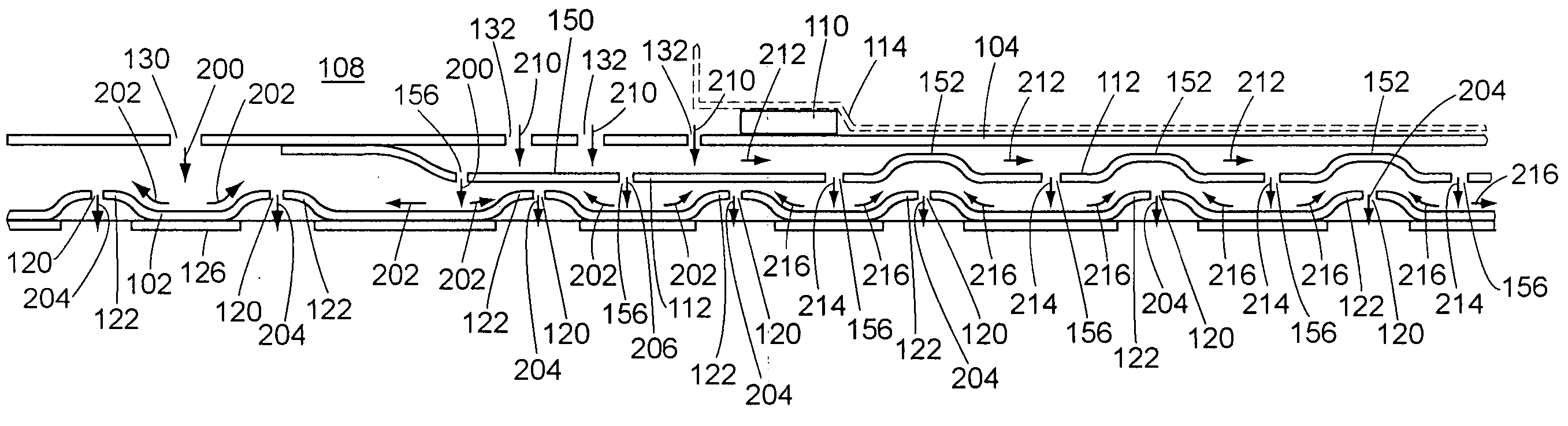
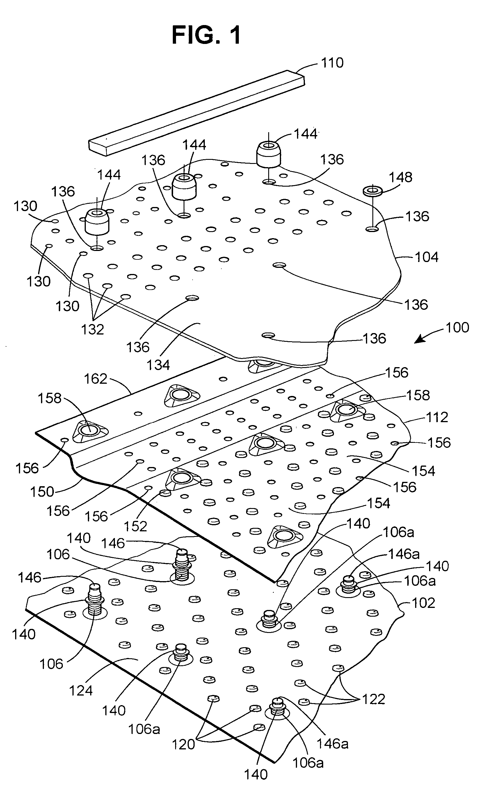
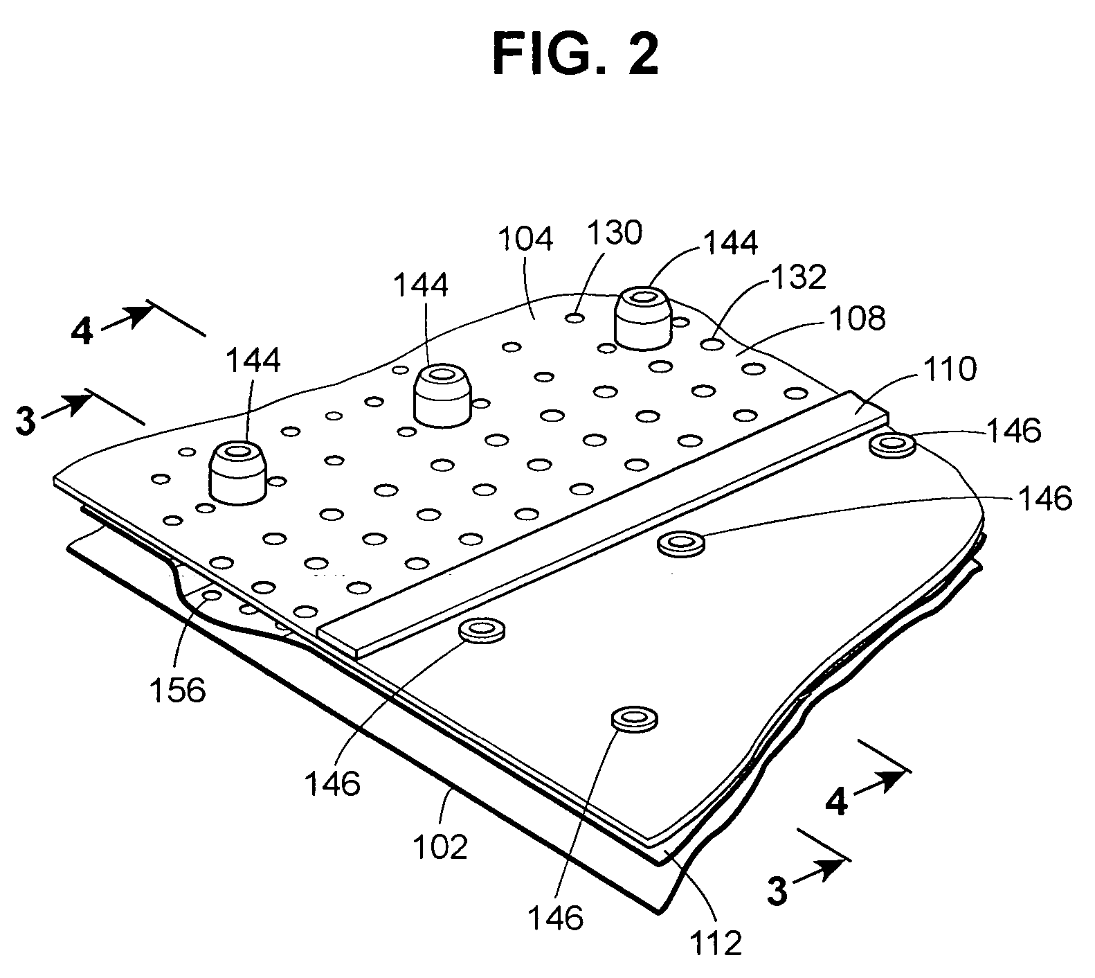
[0016] Referring to FIGS. 1 and 2, a liner 100 for a high temperature application such as the exhaust area of a turbine engine has an inner wall 102, an impingement sheet 104, spacers 106 and 106a, and an air supply plenum 108 having a seal 110. In addition, portions of the liner 100 will have a baffle 112 to direct impingement air, as discussed below, to areas of the inner wall beyond the air supply plenum seal 108. As shown in FIG. 3, an interfering structure 114 (shown in phantom lines), such as an air pump shroud, may prevent the air supply from within the air supply plenum 108 from reaching the portions of the inner wall 102 that lie beyond the extent of the area bounded by air supply plenum seal 110. The structure also includes a tip (not shown) that forms a seal to further direct impingement air through the baffle 112.

[0017] The inner wall 102 has a series of apertures 120. These apertures are located within a series of lands 122. The lands 122 serve to meter the air flow al...


PUM


Abstract

An extended impingement cooling structure to cool outside an air supply plenum comprises an inner wall; an impingement sheet; a series of supports to maintain the inner wall in spaced relation to the impingement sheet, and a baffle supported between the inner wall and the impingement sheet. The baffle has a collector plenum area that receives impingement cooling air from the air supply plenum and a channel in fluid communication with the collector plenum and extending outside the air supply plenum with openings to allow impingement cooling air to pass therethrough and having a series of lands extending into the channel wherein the lands are located in proximity to impingement cooling air outlets in the inner wall.

Description

[0001] This invention was made under a United States Government Contract No. F33657-01-C-1240 and the United States Government may have certain rights to this invention.TECHNICAL FIELD [0002] This invention relates to cooling of portions of a gas turbine engine. More particularly this invention relates to impingement cooling of portions of a liner outside of an air supply plenum. BACKGROUND ART [0003] Impingement cooling has been used in gas turbine engines for some time. Relatively cooler air is taken from the compressor of the engine and passed through a series of holes in an impingement sheet to direct jets of cool air directly onto a surface in need of cooling. For instance in the area downstream from the combustor section of turbine engines impingement cooling has been used to cool the liner to protect parts that may be damaged by high heat from the core gas flow passes over the surface of the liner. The liner has a series of larger holes that are offset from the first series o...

Claims


Application Information

Patent Timeline
Patent Type & Authority Applications(United States)
IPC IPC(8): F01D25/08F02C7/18F23R3/06
CPCF01D25/08F01D25/12F02C7/18F02K1/822F23R3/04F23R2900/03044F05D2260/201Y02T50/60
Inventor MAYER, ROBERTSTONER, CHARLES
Owner RTX CORP
Why Eureka
Try Eureka