Gas flow rate verification unit

a flow rate verification and gas technology, applied in the direction of water supply installation, volume metering, instruments, etc., can solve the problems of affecting the operation of the detoxification device described above, the general processing capacity of the detoxification device is limited, and the gas flow rate is not guaranteed

Active Publication Date: 2010-05-18
CKD
View PDF15 Cites 332 Cited by
  • Summary
  • Abstract
  • Description
  • Claims
  • Application Information

AI Technical Summary

Benefits of technology

[0028]In the gas flow rate verification unit of the present invention which has the above-mentioned configuration, the volume from the first cutoff valve to the second cutoff valve is not more than the volume from the outlet of the flow rate control device to the first cutoff valve, so that the pressure between the first and second cutoff valves is likely to be uniform even if the gas flow rate supplied from the flow rate control device to the portion between the first and second cutoff valves is changed. Therefore, the flow rate verification unit of the present invention can correctly detect the pressure and the temperature between the first and second cutoff valves by the pressure detector and the temperature detector and verify the gas flow rate by use of the results of the pressure detection and the temperature detection. Consequently, according to the gas flow rate verification unit of the present invention, an error of the measured flow rate with respect to changes in the controlled flow rate is reduced, so that reliability of the flow rate verification can be enhanced.
[0029]In the gas flow rate verification unit of the present invention which has the above-mentioned configuration, the first cutoff valve, the second cutoff valve, and the pressure detector are mounted in the channel block to be integrated in a manner that an output port of the first cutoff valve is communicated with a first port of the channel block, an input port of the second cutoff valve is communicated with a second port of the channel block, and the pressure detector is communicated with a third port of the channel block. Thereby, the volume between the first and second cutoff valves can be reduced to downsize the gas flow rate verification unit. Further, by reducing the volume between the first and second cutoff valves is reduced, time taken for the pressure between the first and second cutoff valves to reach the target pressure can be shortened, thereby shortening the verification time of the gas flow rate.
[0031]In the flow rate verification unit of the present invention with the above-mentioned configuration, the gas flow rate verification unit is housed in a gas box including a gas unit in which the flow rate control device is mounted, so that there is no need to change a structure or an external pipe of the gas box for arranging an installation space for the gas flow rate verification unit. Accordingly, the gas flow rate verification unit of the present invention can provide an excellent installation property.
[0032]In the flow rate verification unit of the present invention with the above-mentioned configuration, the control device includes a volume measuring device. The volume measuring device calculates an increasing pressure value per a unit time from the time when the pressure detector detects a fixed initial pressure to the time when the pressure detector detects a target pressure when the gas is filled between the flow rate control device and the second cutoff valve by the target pressure. Concurrently, in the volume measuring device, a gas temperature during the pressure detection is detected by the temperature detector. Then, after measuring a tank volume from the flow rate control device to the second cutoff valve by use of the pressure increase value and the gas temperature, the volume from the first cutoff valve to the second cutoff valve is subtracted from the tank volume to measure the volume from the flow rate control device to the first cutoff valve. Consequently, in the gas flow rate verification unit of the present invention, even if the volume from the outlet of the flow rate control device to the first cutoff valve varies depending upon a system structure in which the unit is mounted, the influence caused by the variation is eliminated, thereby precision in the gas flow rate verification unit can be kept satisfactory.
[0033]In the flow rate verification unit of the present invention with the above-mentioned configuration, the second cutoff valve is connected to a vacuum pump, and the control device is connected to the pressure sensor that detects the pressure between the outlet of the flow rate control device and the first cutoff valve. The control device includes the volume measuring device. In the volume measuring device, when the portion between the first cutoff valve and the second cutoff valve is evacuated by the vacuum pump, and then the gas filled between the flow rate control device and the first cutoff vale is discharged between the first and second cutoff valves, the tank volume from the flow rate control device to the second cutoff valve is measured by use of the pressure change and the temperature change between the first and second cutoff valves to subtract the volume from the first cutoff valve to the second cutoff valve from the tank volume, thus measuring the volume from the flow rate control device to the first cutoff valve. Consequently, according to the gas flow rate verification unit of the present invention, even if the volume from the flow rate control device to the first cutoff valve varies depending upon the system structure in which the unit is mounted, the influence caused by the variation is eliminated, so that the precision in the gas flow rate verification can be kept satisfactory.
[0034]In the flow rate verification unit of the present invention with the above-mentioned configuration, a gradient of the pressure value detected by the pressure detector or correlation coefficient with respect to the gradient of the pressure value are calculated, and the flow rate of the gas is verified when the calculated gradient or the correlation coefficient become within a measurable range. Therefore, the flow rate verification can be performed without waiting a dead time for stabilizing the pressure detector to detect a measurement start pressure, and accordingly the flow rate verification time can be shortened.

Problems solved by technology

Another reason is that most of these gases are harmful to a human body and environment or have explosiveness.
However, the detoxifying device described above has limited processing capacity in general.
Therefore, when the flow rate more than the allowable value flows, it cannot perfectly process the gas, so that the deleterious gas might be flown out in the atmosphere or the detoxifying device might be broken.
Moreover, since these gases, especially high-purity dust-free gas that can be used in a semiconductor manufacturing process, are expensive, and limitation is imposed on some gases for their use due to natural deterioration, they cannot be preserved in a large quantity.
However, these gases used in the semiconductor manufacturing process, especially the material gas for the film deposition among the so-called process gases, might cause precipitation of solid substances in a gas line due to its characteristics, so that the flow volume might be changed.
Even a small amount of precipitation of the solid substance on this portion could deteriorate the flow precision of the gas to be supplied.
Further, since a gas with high corrosivity for an etching process or the like is flown, the corrosion of the mass flow controller cannot be avoided even if a material having a high corrosion resistance such as a stainless material or the like is used.
As a result, a secular deterioration could occur, deteriorating the flow precision.
Therefore, the work is very time-consuming.

Method used


Image

  • Gas flow rate verification unit
  • Gas flow rate verification unit
  • Gas flow rate verification unit

Examples


first embodiment

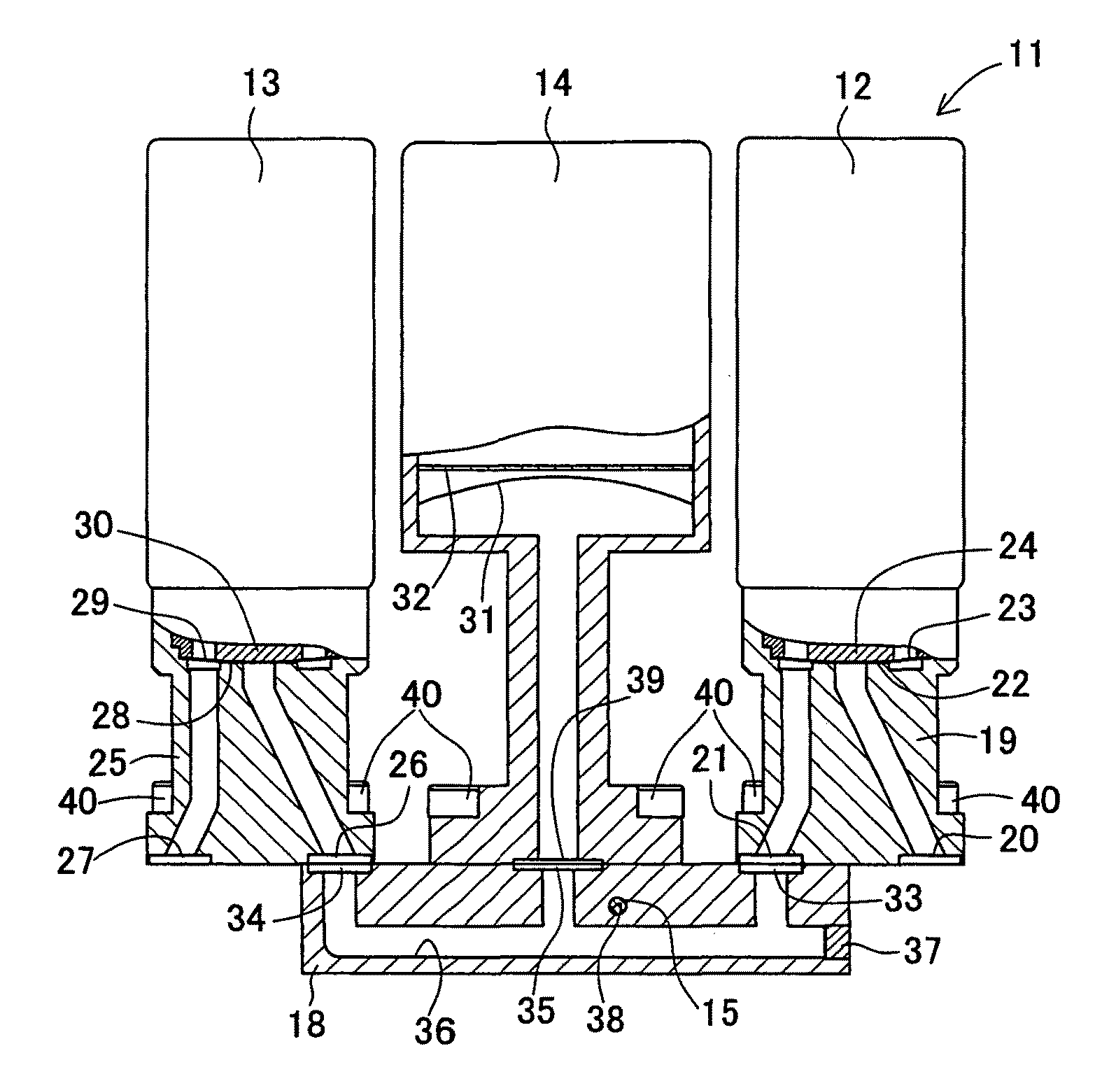
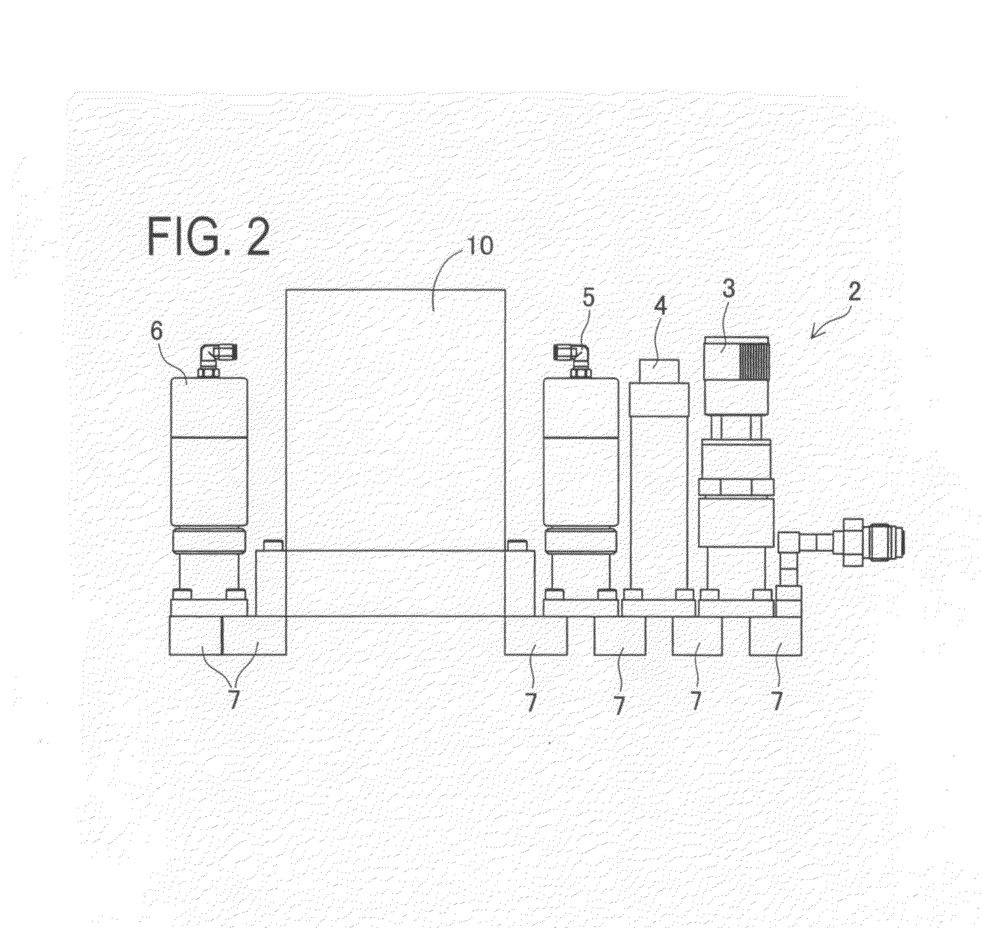
[0070]FIG. 1 is a schematic structural view of a gas box 1 having a gas flow rate verification unit 11 incorporated therein. FIG. 2 is a side view of a gas unit 2 shown in FIG. 1.

[0071]As shown in FIG. 1, the gas flow rate verification unit 11 is mounted in the gas box 1, for example. The gas box 1 has a box-like shape and a gas supply integration unit having plural (twelve in FIG. 1) gas units 2 integrated therein. As shown in FIGS. 1 and 2, each of the gas units 2 includes a fluid control device such as a regulator 3, a pressure gauge 4, an input cutoff valve 5, a mass flow controller 10 which is one example of a “flow rate control device”, an output cutoff valve 6, and the like each being fixed on an upper surface of a channel block 7 and integrally coupled in series.

[0072]As shown in FIG. 1, an installation space for installing a pipe 8 for charging a process gas from each gas unit 2 is provided between the gas units 2 and the gas box 1. In the installation space, the surroundin...

second embodiment

[0149]The second embodiment of the gas flow rate verification unit according to the present invention will be explained with reference to the drawings. FIG. 11 is a block diagram showing one example of a gas supply integration unit 63 provided with a gas flow rate verification unit 11A.

[0150]The gas flow rate verification unit 11A according to the second embodiment is used for performing the flow rate verification of the gas supply integration unit 63 shown in FIG. 11. The circuit structure of the gas supply integration unit 63 is the same as that of the evaluation device 50 (see FIG. 8) described in the first embodiment, so that the numerals same as those in the evaluation device 50 are given to the fluid control devices. The structure of the controller 61 in the gas flow rate verification unit 11A according to the second embodiment is different from the controller 16 in the first embodiment. Therefore, the points different from the first embodiment will mainly be explained, and th...

third embodiment

[0161]The third embodiment of the gas flow rate verification unit according to the present invention will be explained with reference to the drawings.

[0162]A gas flow rate verification unit 11B according to the third embodiment is obtained by improving the flow rate verification process of the gas flow rate verification unit 11 in the first embodiment in order to shorten the flow rate verification time. Therefore, the points different from the first embodiment will mainly be explained, and the same referential codes in the first embodiment are given to the same components in the figures for suitably omitting the explanations thereof.

[0163]FIG. 13 is a flowchart showing a gas flow rate verification method executed by the gas flow rate verification unit 11B according to the third embodiment. FIG. 14 is a graph showing data obtained by sampling the pressure values detected by the pressure sensor at an interval of a predetermined time in the gas flow rate verification unit according to ...


PUM


Abstract

A gas flow rate verification unit capable of enhancing reliability of gas flow rate verification. The gas flow rate verification unit has a first cutoff valve that is connected to a flow rate control device and to which gas is inputted, a second cutoff valve for discharging the gas, a communication member for allowing the first cutoff valve and the second cutoff valve to communicate with each other, a pressure sensor for detecting the pressure of the gas supplied between the first cutoff valve and the second cutoff valve, a temperature detector for detecting the temperature of the gas supplied between the first cutoff valve and the second cutoff valve, and a control means for verifying the flow of the gas flowing in the flow control device, the verification being performed by using both the result of the pressure detected by the pressure sensor and the result of the temperatures detected by the temperature detector. The volume (Vk) between the valve seat of the first cutoff valve and the valve seat of the second cutoff valve is equal to or less than the volume (Ve) between the outlet of the flow control device and the valve seat of the first cutoff valve.

Description

TECHNICAL FIELD[0001]The present invention relates to a gas flow rate verification unit that verifies a flow rate of a flow rate control device used in a gas system in a semiconductor manufacturing process.BACKGROUND ART[0002]In a film deposition device or a dry etching device in a semiconductor manufacturing process, special gas such as silane or phosphine, corrosive gas such as chlorinated gas, combustible gas such as hydrogen gas, or the like are used.[0003]Flow rates of these gases should strictly be controlled.[0004]The reason of this is because the gas flow rate directly affects a quality of the process. Specifically, the gas flow rate greatly affects a film quality in a film deposition process or a quality of a circuit processing in an etching process, whereby a yield of a semiconductor product is determined according to precision of the gas flow rate.[0005]Another reason is that most of these gases are harmful to a human body and environment or have explosiveness. These gase...

Claims


Application Information

Patent Timeline
Patent Type & Authority Patents(United States)
IPC IPC(8): G01F1/00G01F1/34G01F25/00
CPCG01F1/383G01F25/0007G01F15/005G01F1/50Y10T137/0379Y10T137/87249G01F25/10G01F25/00G01F1/34G01F3/22
Inventor OZAWA, YUKIOITO, MINORUDOI, HIROKINAKADA, AKIKO
Owner CKD
Why Eureka
Try Eureka