
Substrate Processing Apparatus

a substrate processing and substrate technology, applied in the direction of crystal growth process, polycrystalline material growth, chemically reactive gas growth process, etc., can solve the problems of increasing the manufacturing cost and installation space (footprint) reducing the quality or process yield of the substrate processing, and complicating the structure of the substrate processing apparatus

Inactive Publication Date: 2010-03-11
KOKUSA ELECTRIC CO LTD
View PDF1 Cites 342 Cited by
  • Summary
  • Abstract
  • Description
  • Claims
  • Application Information

AI Technical Summary

Benefits of technology

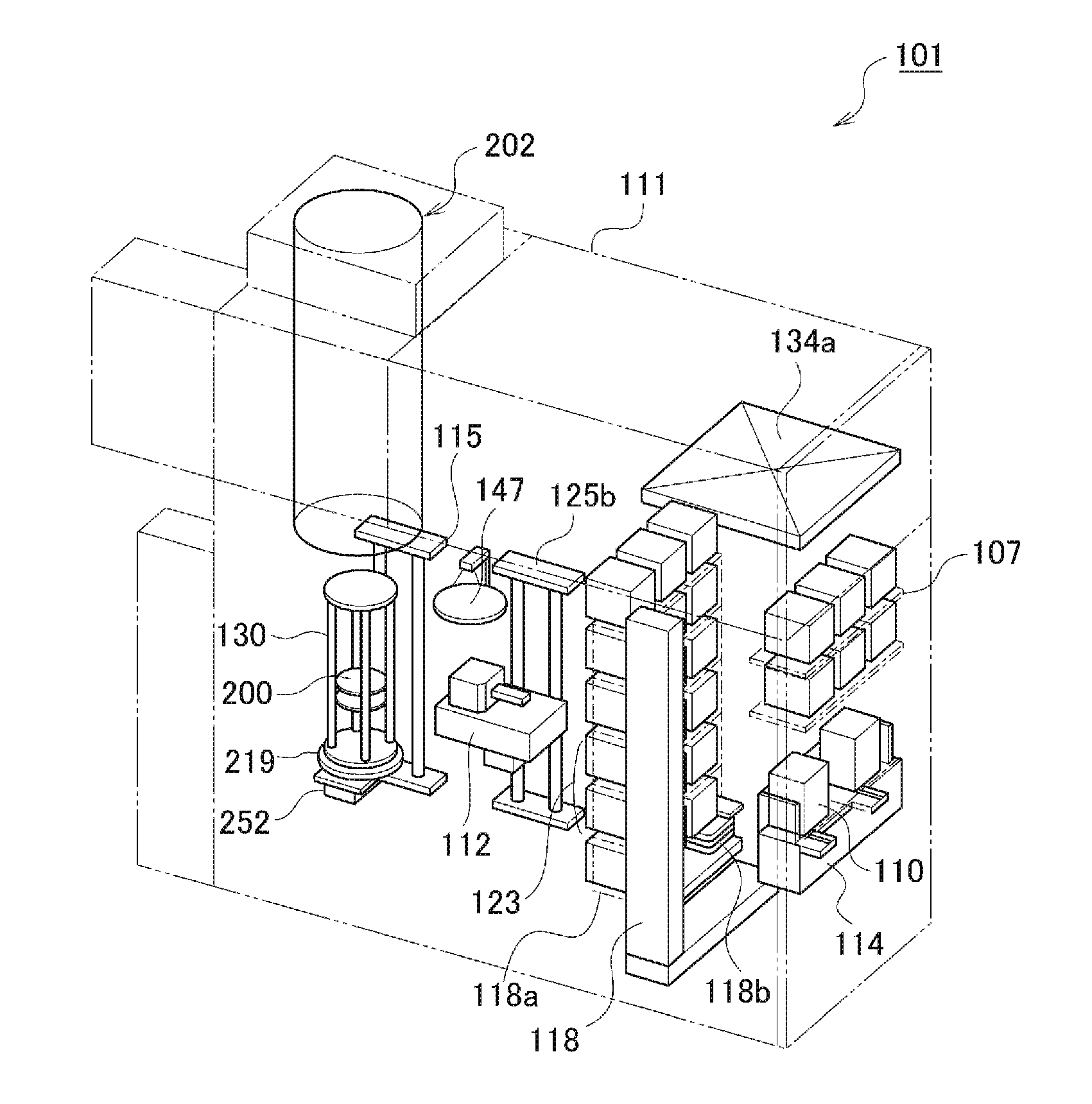
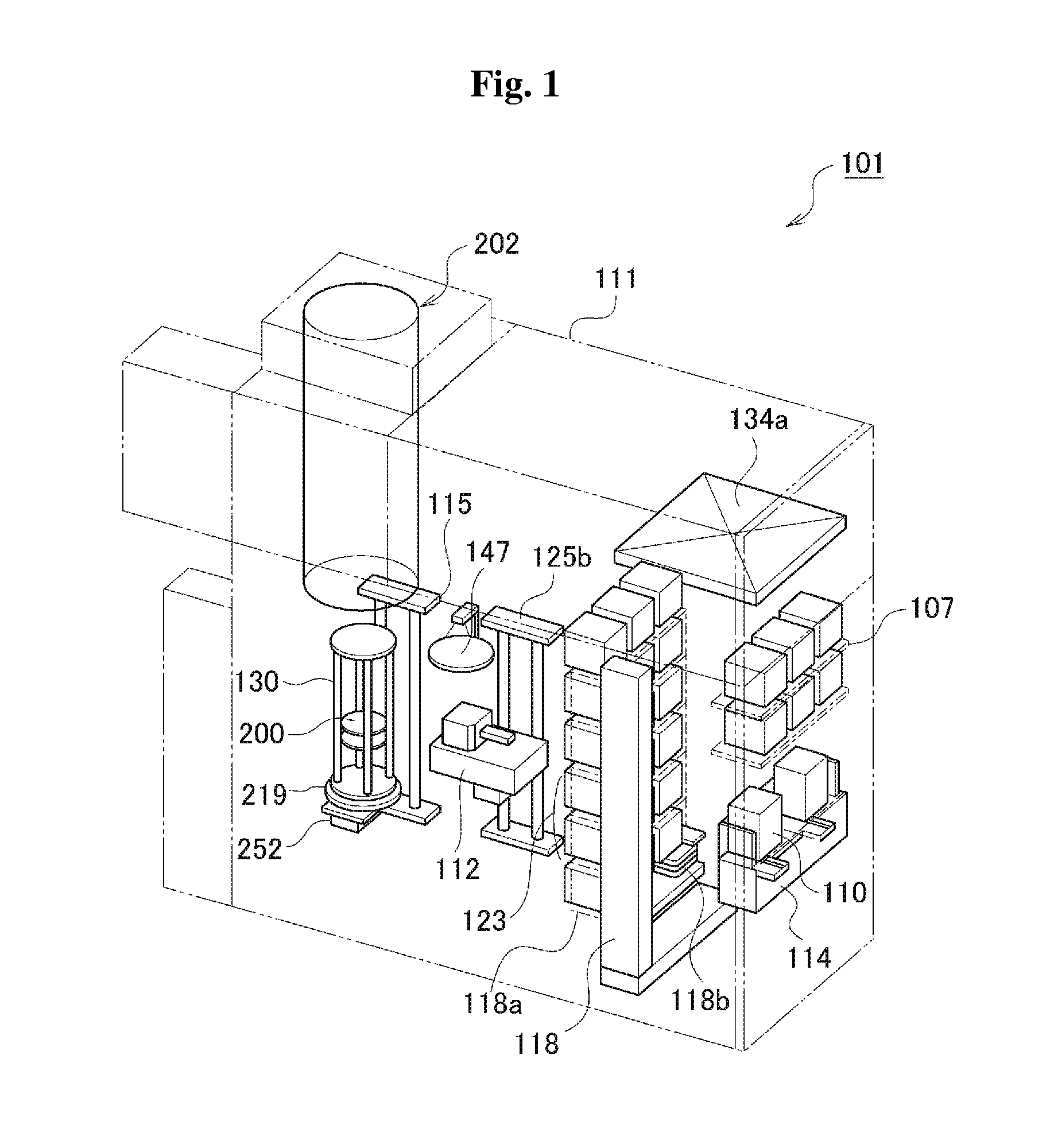
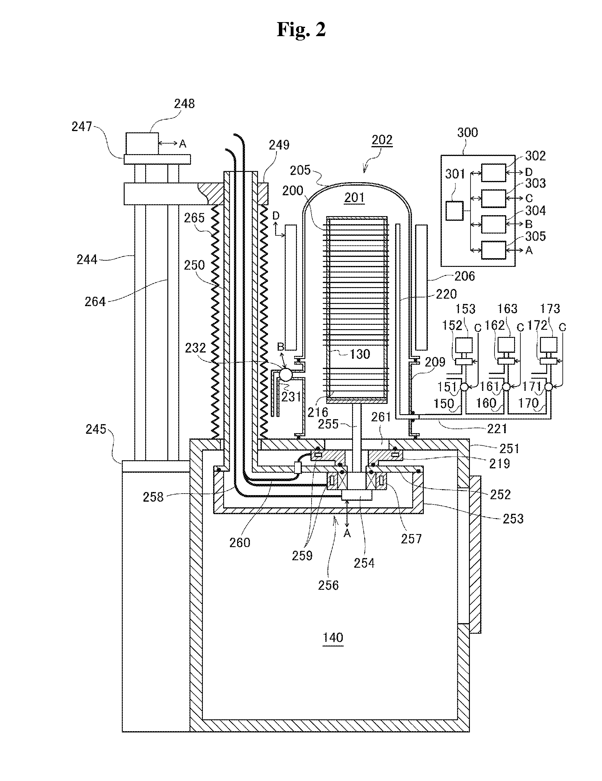
The present invention provides a substrate processing apparatus that can prevent process gas from diffusing back into the process chamber without the need for a dedicated vacuum pump. This is achieved by using a bypass pipe connected between the gas supply system and the gas exhaust system, with two or more vacuum pumps installed in series at the gas exhaust system. The most upstream vacuum pump is a mechanical booster pump, and the bypass pipe is connected between the mechanical booster pump and the rest vacuum pumps located at a downstream side of the mechanical booster pump. This results in improved gas exhaust and reduced gas diffusion back into the process chamber, leading to improved substrate processing efficiency.

Problems solved by technology

In this case, substances such as contaminants remaining in the gas exhaust system may permeate into the process chamber together with the process gas, and thus the substrate processing quality or process yield may be decreased.
However, this may complicate the structure of the substrate processing apparatus and increase the manufacturing costs and installation space (footprint) of the substrate processing apparatus.

Method used


Image

  • Substrate Processing Apparatus
  • Substrate Processing Apparatus
  • Substrate Processing Apparatus

Examples


Embodiment Construction

[0019]An epitaxial silicon film (Epi-Si film) or an epitaxial silicon germanium film (Epi-SiGe film) can be grown on a substrate by supplying process gas to the inside of a process chamber in which the substrate is accommodated. For growing an epitaxial film, it may be necessary to maintain the flowrate of process gas more stably as compared with the case of growing a polysilicon film (Poly-Si film).

[0020]For example, in the case of growing an Epi-SiGe film on a silicon substrate, silane-based gas such as SiH4 gas and Si2H6 gas, and germanium-based gas such as GeH4 gas, or chlorine-based gas such as Cl2 gas are sequentially or simultaneously supplied to the inside of a process chamber, and it is necessary to stabilize the flowrates of gases supplied to the inside of the process chamber so as to control the ratio of silicon (Si) and germanium (Ge) precisely. In addition, gas such as B2H6 gas diluted with H2 gas may be supplied the inside of the process chamber to dope the Epi-SiGe fi...


PUM

PropertyMeasurementUnit
timeaaaaaaaaaa
pressureaaaaaaaaaa
temperatureaaaaaaaaaa

Abstract

Process gas discharged from a bypass pipe to a gas exhaust system can be prevented from diffusing back to the inside of a process chamber without having to install a dedicated vacuum pump at the downstream side of the bypass pipe. The substrate processing apparatus includes a process chamber accommodating a substrate, a gas supply system supplying process gas from a process gas source to the process chamber for processing the substrate, a gas exhaust system configured to exhaust the process chamber, two or more vacuum pumps installed in series at the gas exhaust system, and a bypass pipe connected between the gas supply system and the gas exhaust system. The most upstream one of the vacuum pumps is a mechanical booster pump, and the bypass pipe is connected between the mechanical booster pump and the rest vacuum pumps located at a downstream side of the mechanical booster pump.

Description

CROSS-REFERENCE TO RELATED PATENT APPLICATION[0001]This U.S. non-provisional patent application claims priority under 35 U.S.C. §119 of Japanese Patent Application No. 2008-232618, filed on Sep. 10, 2008, in the Japanese Patent Office, the entire contents of which are hereby incorporated by reference.BACKGROUND OF THE INVENTION[0002]1. Field of the Invention[0003]The present invention relates to a substrate processing apparatus configured to process a substrate.[0004]2. Description of the Prior Art[0005]Films such as an epitaxial silicon film (Epi-Si film) and an epitaxial silicon germanium film (Epi-SiGe film) can be grown on a substrate by supplying process gas to the inside of a process chamber in which the substrate is accommodated. For growing an epitaxial film, it may be necessary to stabilize the flowrate of process gas supplied to the inside of the process chamber. For this end, prior to the supply of process gas to the inside of the process chamber, the inside of the proces...

Claims


Application Information

Patent Timeline
Patent Type & Authority Applications(United States)
IPC IPC(8): C23C16/00
CPCC23C16/24C23C16/30C30B29/06C30B25/14C23C16/4412
Inventor MARUBAYASHI, TETSUYAMORIYA, ATSUSHI
Owner KOKUSA ELECTRIC CO LTD
Learn More