
Wane orientation board turner

Inactive Publication Date: 2005-07-14
USNRKOCKUMS CANCAR
View PDF11 Cites 24 Cited by
  • Summary
  • Abstract
  • Description
  • Claims
  • Application Information

AI Technical Summary

Benefits of technology

[0012] In a planer mill operation, by way of example, all lumber carried by the lugged transfer must be previously sorted so that the wane end is remote from the fixed planer knives. The board turner must operate to invert boards so that the wane side is uppermost. This allows the adjustable planer knives to remove sufficient wood to produce a high quality finished board.
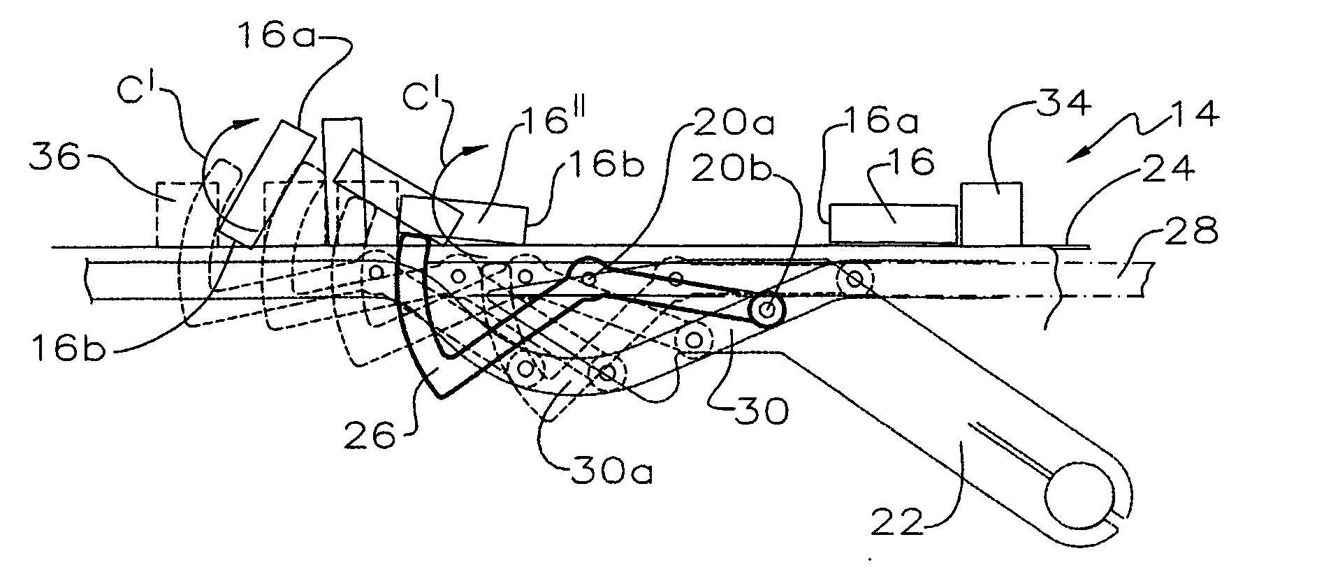
[0014] A continuously operating smooth surfaced speed-up friction belt or chain is positioned laterally of the high-speed board turning device. The speed of rotation of the speed-up friction belt is substantially faster than that of the lugged board transfer so that any lumber piece contacting the speed-up means is accelerated from the upstream transporting lug to the adjacent downstream lug within the same one lug space of the lugged board transfer. When the lumber piece has been sped-up within its lug space so as to be brought into contact with or adjacent to the downstream lug of the lugged board transfer, a corresponding turning arm moving at the speed of, and in the direction of the board transfer, enters the divergent dip path zone, that is where the follower wheel follows the dip in the track, so that the arcuate contact leg of the turning arm is elevated to contact the leading edge of the lumber piece on the downstream lug. Further elevation of the turning arm in concert with the rapidly moving speed-up friction belt still accelerating the non-elevated edge of the lumber piece results in forward movement of the non-elevated edge, that is the trailing edge of the lumber piece under and ahead of the forward elevated edge with the result that the lumber piece is inverted 180 degrees about its longitudinal axis.

Problems solved by technology

Prior art board turners previously used are incapable of evaluating the correct face and edge solutions together, and therefore only consider one or the other.
Rotation of the friction conveyor results in forward movement of the trailing edge of the board with the result that the board rides upwardly and rearwardly against the turner arm flipping the board over backwards.

Method used


Image

  • Wane orientation board turner
  • Wane orientation board turner
  • Wane orientation board turner

Examples


Embodiment Construction

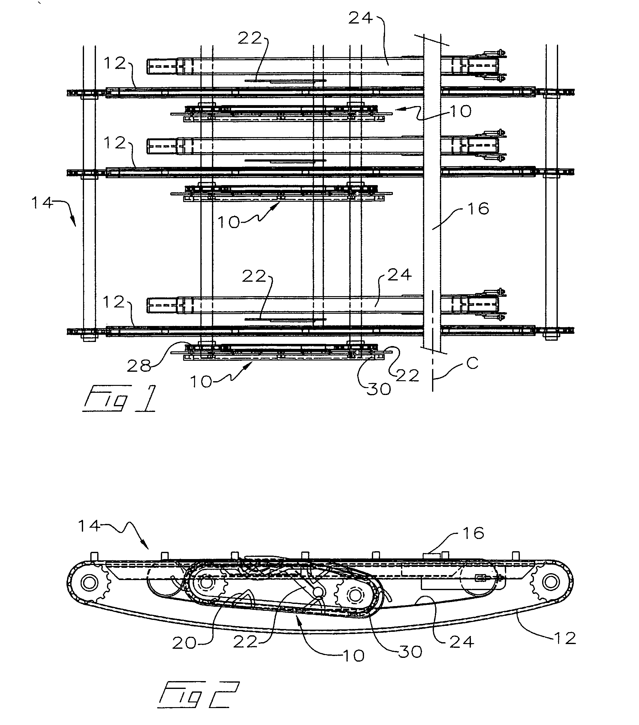
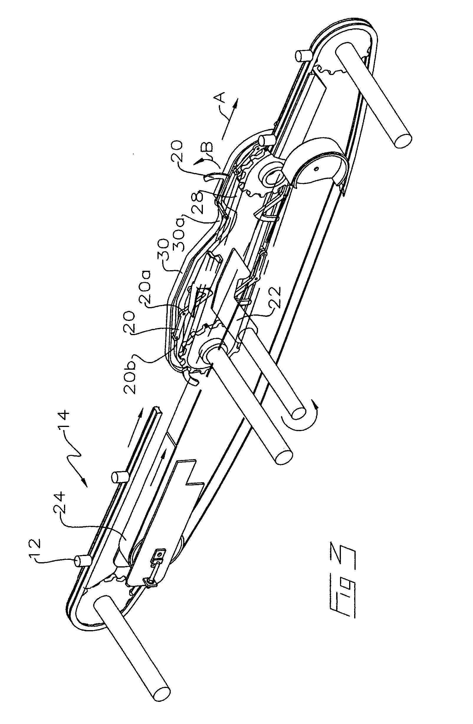
[0034] With reference to the drawing figures, wherein similar characters of reference denote corresponding parts in each view, the high speed board turner 10 of the present invention is positioned in proximity to the plurality of chains 12 of a lugged transfer 14 common to sawmill and planer mill applications. Scanners or optimisers (not shown) normally assess lumber pieces 16 carried on lugged transfer 14 to identify wane 18 and the like defects, prior to approaching board turner 10.

[0035] Board turner 10 includes a board turning arm 20, a lift skid 22 and a speed-up belt 24. A plurality of turning arms 20 are rotatably mounted to drive chain 28. Chain 28 is positioned adjacent and parallel to one side of arms 20. Arms 20 are also mounted to a track 30 positioned on the other side of arms 20. Connecting pins 20a pivotally mount arms 20 to chain 28. Pins 20b mount the track follower ends of arms 20 to the wheels which run in the track. An arcuately shaped board contact leg 26 is lo...


PUM


Abstract

A device for selectively inverting a workpiece about the longitudinal axis of the workpiece within a single lug space of a lugged transfer without impeding lumber flow along a flow path on the lugged transfer, wherein the device includes a workpiece speed-up for urging the workpiece at an increased translation speed along the flow path, a selectively operable workpiece brake to inhibit accelerated translation of the workpiece by the workpiece speed-up so as to selectively at least momentarily delay translation of the workpiece at the increased translation speed of the workpiece speed-up, and a workpiece turning arm mounted downstream along the workpiece speed-up. The board turning arm is selectively actuable into the flow path so as to invert the workpiece about its longitudinal axis within a corresponding lug space of the lugged transfer once the workpiece has been translated by the speed-up to a downstream end of the corresponding lug space.

Description

CROSS REFERENCE TO RELATED APPLICATION [0001] This application claims priority from U.S. Provisional Patent Applications No. 60 / 534,684 filed Jan. 8, 2004 and No. 60 / 549,167 filed Mar. 3, 2004 both entitled Wane Orientation Board Turner.FIELD OF THE INVENTION [0002] This invention relates to a high-speed board turner for selectively inverting lumber pieces of varying widths 180 degrees about their longitudinal axis while the board remains within the same lug space of a lugged transfer and without varying the speed of the lugged transfer. The board turner is located in front of a planer, and is used to maximize the grade recovery of a piece of wood by allowing the worst face and edge to be oriented away from the linebar and bed plate. BACKGROUND OF THE INVENTION [0003] Wane orientation has normally been done within a sawmill where a photo eye or scanner has identified a round back or a wane in a board for grade evaluation or trimming. Further optimising can then identify the finished...

Claims


Application Information

Patent Timeline
IPC IPC(8): B27B31/04B65G47/24B65G47/248B65G47/252
CPCB65G47/248B65G2201/0282B65G47/252
Inventor HENDERSON, DEANE
Owner USNRKOCKUMS CANCAR
Learn More