
Mouth tube portion of synthetic resin bottle body

a synthetic resin bottle and bottle body technology, applied in the direction of refusing gathering, venting, other domestic objects, etc., can solve the problems of too short a time left to loosen the molecular orientation, and it is difficult to reduce the difference in molecular orientation fully within the practical range of thickness

Inactive Publication Date: 2005-07-14
YOSHINO KOGYOSHO CO LTD
View PDF12 Cites 15 Cited by
  • Summary
  • Abstract
  • Description
  • Claims
  • Application Information

AI Technical Summary

Benefits of technology

The invention relates to a new configuration for the neck of a synthetic resin bottle that solves the technical problem of surface sinks on the top surface of the neck caused by the intermittent thread ridge structure. The new configuration includes a gas-venting groove that is formed in the thread ridge, leaving a part of the thread ridge up to a certain height. This configuration reduces the difference in molecular orientation between the thread ridge and the missing parts of the thread ridge, which results in a smaller difference in shrinkage. The new configuration also inhibits distortion and prevents the contents of the bottle from spilling over or spouting out under reduced pressure conditions. The patent text describes various means for carrying out the invention, including the use of a gas-venting groove with a certain height, the formation of the gas-venting groove at a central angle, and the disposition of the gas-venting groove in a nearly straight direction across the rows of the spiral thread ridge.

Problems solved by technology

Thus, too short a period of time is left to loosen the molecular orientation, and the difference in the molecular orientation, which has developed during the flow, stays behind in the molded product under these circumstances.
However, as described above, from the aspects of productivity, cost reduction, and resources saving of the PET bottles, it is difficult to reduce the difference in molecular orientation fully within a practical range of thickness.

Method used


Image

  • Mouth tube portion of synthetic resin bottle body
  • Mouth tube portion of synthetic resin bottle body
  • Mouth tube portion of synthetic resin bottle body

Examples


Embodiment Construction

[0048] This invention is further described with respect to a preferred embodiment, now referring to FIG. 1 through FIG. 6.

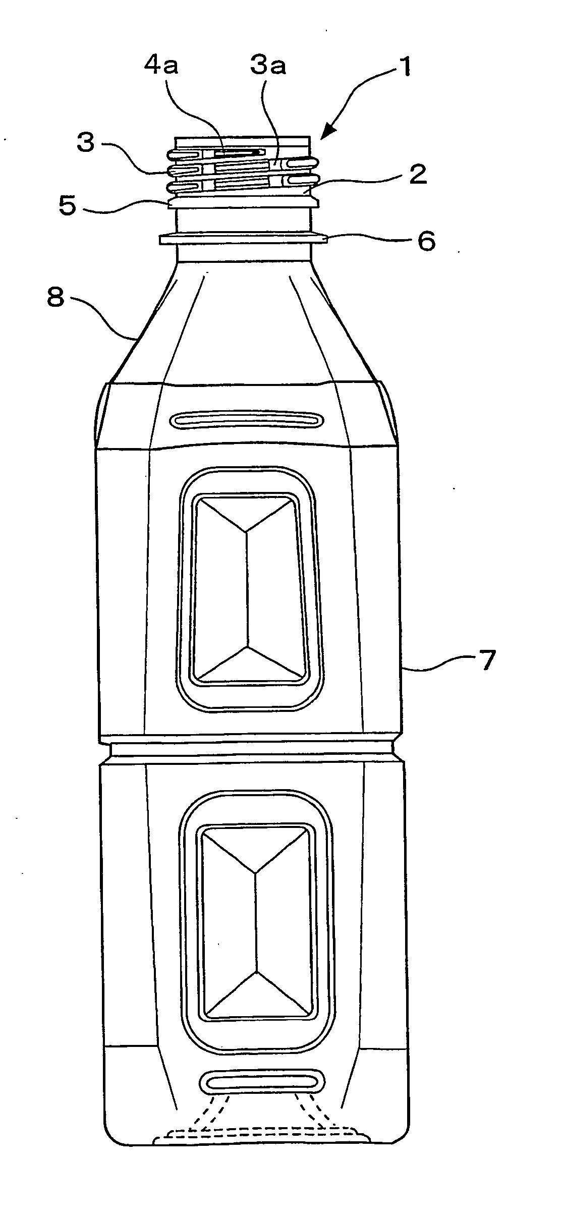
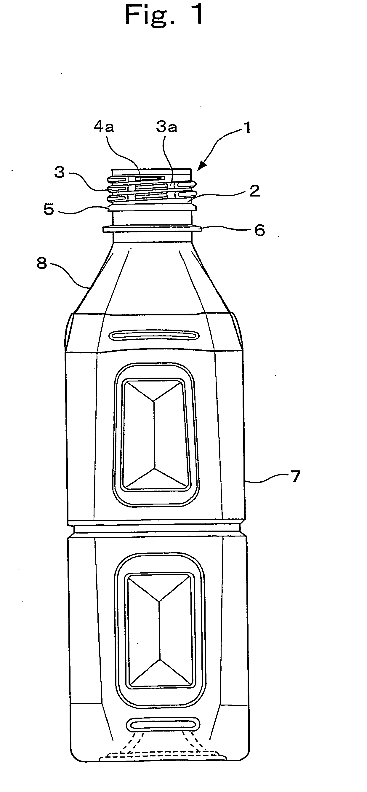
[0049]FIG. 1 is a front elevational view of the bottle in the preferred embodiment of this invention. The bottle is a biaxially drawn and blow-molded bottle made of a polyethylene terephthalate resin. The neck 1 of this invention stands on the upper end of the body 7 in the bottomed square shape by way of shoulder 8 in the truncated pyramid shape.

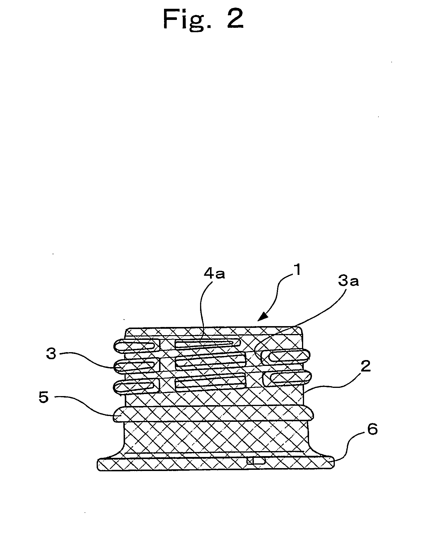
[0050] The thread ridge 3 on the neck 1 is carved at a length of about two and a half coils in the upper half area on the outer surface of the cylindrical neck wall 2. The bead ring 5 and the neck ring 6 are disposed in the corresponding lower half area of the round wall 2.

[0051] The neck 1 of this embodiment is whitened by the thermal crystallization. The mesh hatching over the neck 1 in FIGS. 2, 3, and 4 shows the neck in the whitened state. (This hatching is omitted in FIGS. 1 and 5.) In this embodiment, the neck 1...


PUM

PropertyMeasurementUnit
central angleaaaaaaaaaa
curvature radiusaaaaaaaaaa
central angleaaaaaaaaaa

Abstract

The gas-venting groove or grooves are formed, while leaving a part of the thread ridge (3) up to a certain height, as the vertical degassing paths in the thread ridge carved on the outer surface of the round neck wall and the entire neck is whitened by the thermal crystallization. This thermal crystallization is conducted under the condition that the neck is prevented from undesired deformation caused by uneven resin flow state. Thus, the object of this invention is to provide a highly safe neck that can be used widely in the field of heat-resistant containers, pressure-tight containers, and heat-resistant and pressure-tight containers.

Description

TECHNICAL FIELD [0001] This invention relates to a neck structure of the synthetic resin bottle that is drawn and blow-molded from a polyethylene terephthalate resin and the like. BACKGROUND ART [0002] Japanese patent application No. P1998-58527 includes a description on a biaxially drawn, blow-molded bottle made of a polyethylene terephthalate resin (hereinafter referred to as PET bottle) and used for the beverage products, such as tea and fruit juices, and the like, which require a filling operation at a high temperature or a thermal treatment process. The so-called heat-resistant neck has high thermal deformation resistance strengthened by the thermal crystallization treatment, and is used as the neck of the PET bottle which is to be filled with tea, fruit juice, liquid seasoning and the like at a high temperature, or is subjected to a thermal treatment process. [0003]FIG. 10 shows a typical PET bottle to be filled with tea, fruit juice, and the like. FIGS. 11 and 12 show a typic...

Claims


Application Information

Patent Timeline
Patent Type & Authority Applications(United States)
IPC IPC(8): B65D1/02B65D51/16B65D79/00
CPCB29K2995/0016B29K2995/0041B29K2995/0043B29L2031/7158B65D1/0246Y10S215/902B65D79/005B65D2205/00B29B2911/14446Y10S220/913B65D51/1688B29C2949/0774B29C49/42832B29C49/6452B65D1/02B65D1/46
Inventor OZAWA, TOMOYUKITANAKA, TOSHIMASAIIZUKA, TAKAOTAKADA, MAKOTO
Owner YOSHINO KOGYOSHO CO LTD
Learn More