Converter and inverter including converter circuit

a converter circuit and inverter technology, applied in the field of converters, can solve the problems of large scale of converters or inverters, and achieve the effect of increasing the capacitance of capacitors and facilitating energy supply

Inactive Publication Date: 2005-07-14
FANUC LTD
View PDF14 Cites 12 Cited by
  • Summary
  • Abstract
  • Description
  • Claims
  • Application Information

AI Technical Summary

Benefits of technology

[0012] Accordingly, an object of the present invention is to solve the foregoing problems underlying the related arts and to facilitate supply of energy from a voltage smoothing capacitor to a load or recovery of energy from the load without the necessity of increasing the capacitance of the capacitor.

Problems solved by technology

However, if the capacitance of the voltage smoothing capacitor is increased, the scale of the converter or inverter becomes larger.

Method used


Image

  • Converter and inverter including converter circuit
  • Converter and inverter including converter circuit
  • Converter and inverter including converter circuit

Examples


Embodiment Construction

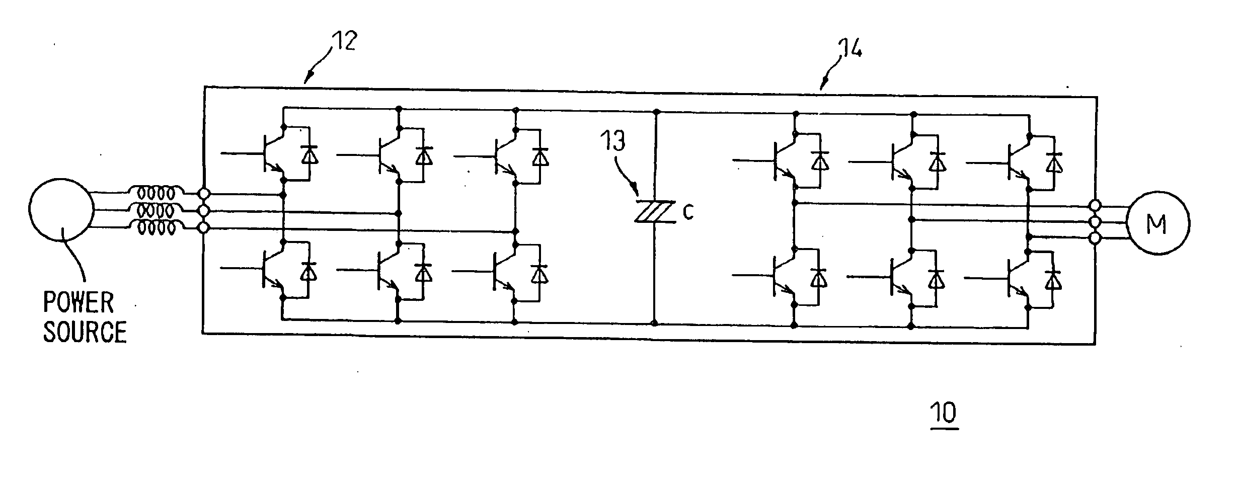
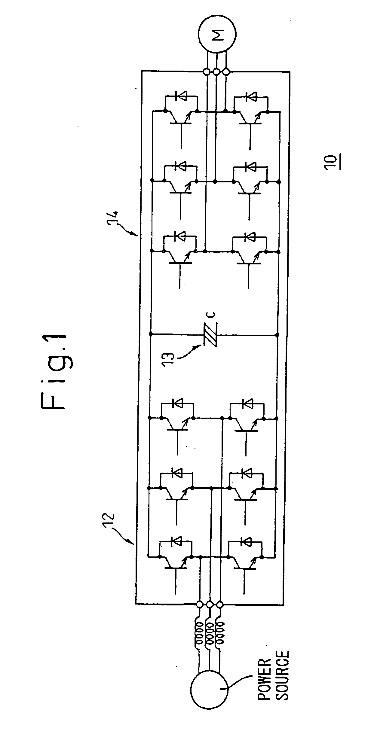
[0035]FIG. 1 is an explanatory diagram schematically showing an inverter in accordance with the present invention. An inverter 10 shown in FIG. 1 comprises a converter circuit 12 that converts an ac voltage applied from an ac power supply into a dc voltage, a voltage smoothing capacitor 13, and an inverter circuit 14 that inverts a dc voltage into an ac voltage of a predetermined frequency and applies the ac voltage to a load (a motor M).

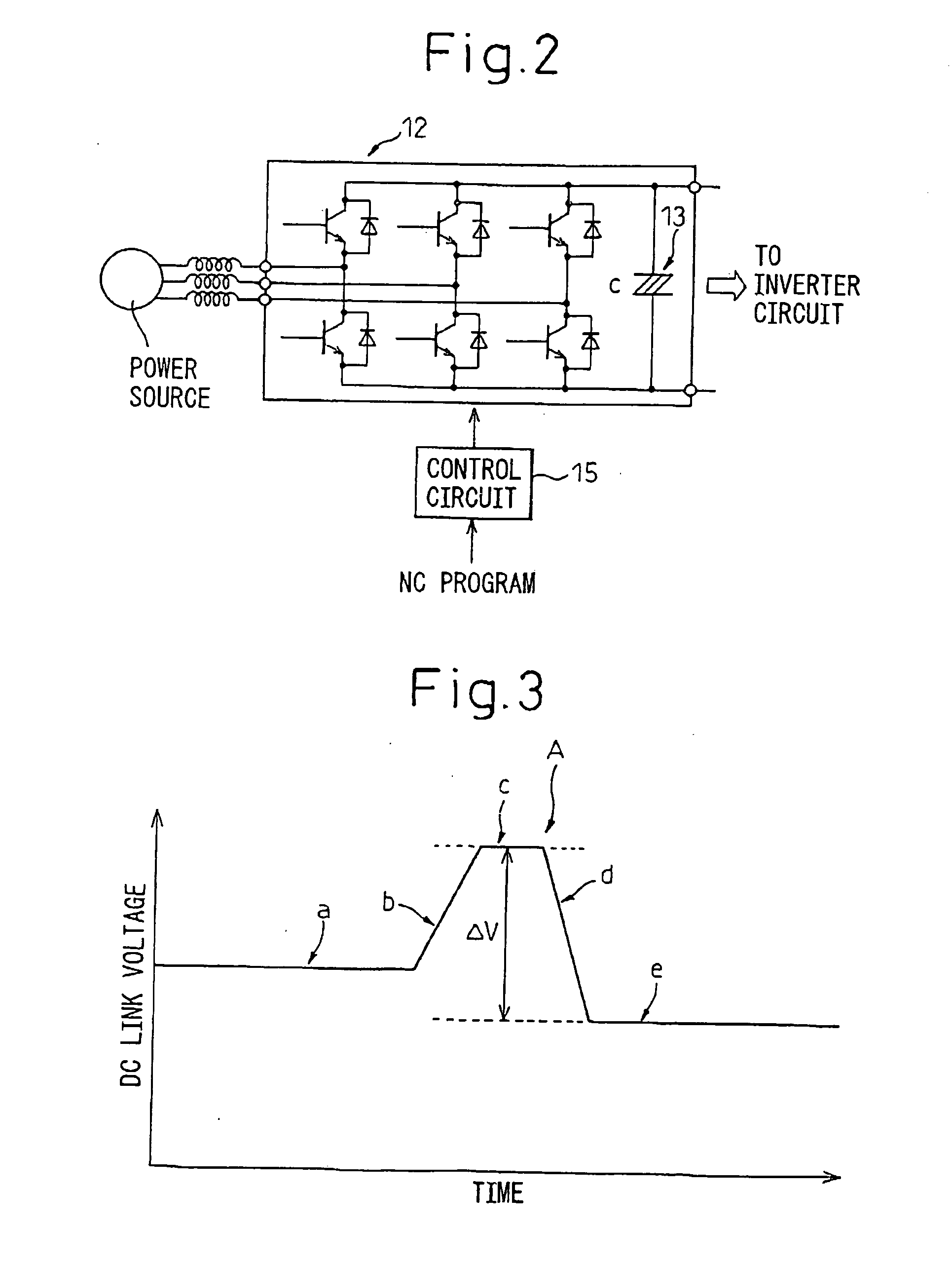
[0036] In the inverter 10 of the present invention, the converter circuit 12 controls a do link voltage. FIG. 2 shows an example of the configuration of the converter circuit. The converter circuit 12 is controlled by PWM to allow a control circuit 15 to switch the on and off states of transistors such as IGBTs. The technology of retaining a dc link voltage at a predetermined value using a PWM is well-known. A control target value of the dc link voltage is dynamically changed in order to dynamically control the do link voltage. For example, in a nu...


PUM


Abstract

In an inverter comprising a converter circuit that converts an alternating current into a direct current and an inverter circuit that inverts the direct current into the alternating current, supply of energy from a voltage smoothing capacitor to a load or recovery of energy from the load is facilitated without the necessity of increasing the capacitance of the voltage smoothing capacitor interposed between the converter circuit and inverter circuit. In the converter circuit, before the supply of energy to the load is started, the voltage on a dc link is raised. Before collection of energy from the load is started, the voltage on the dc link is lowered.

Description

BACKGROUND OF THE INVENTION [0001] 1. Field of the Invention [0002] The present invention relates to a converter, to an inverter including a converter circuit and, more particularly, to the control of a dc link voltage in the converter and the inventor. [0003] 2. Description of the Related Art [0004] Inverters convert an applied direct current (dc) into an alternating current (ac), and are used to, for example, drive an induction motor. The inverter coverts an applied dc voltage into an ac voltage by performing pulse width control, etc. [0005] An inverter having the following configuration is also known: a converter circuit that converts an ac voltage applied from an ac power supply into a do voltage is connected to an inverter circuit (dc link); and a dc link voltage provided by the converter circuit is used as an input of the inverter circuit. [0006] In the converter or the inverter including the converter circuit, a capacitor is often connected on the dc link between the converte...

Claims


Application Information

Patent Timeline
Patent Type & Authority Applications(United States)
IPC IPC(8): H02M7/12H02M5/458H02M7/797
CPCH02M5/4585
Inventor YAESHIMA, MAMORUHANYU, SHIGEKIKAGAMI, HIDEKIYAMADA, YUUICHI
Owner FANUC LTD
Why Eureka
Try Eureka