High frequency measurement for current-in-plane-tunneling

a technology of current-in-plane tuning and high frequency measurement, which is applied in the direction of resistance/reactance/impedence, individual semiconductor device testing, instruments, etc., can solve the problems of difficult mechanical improvement of the measurement system to eliminate this miniscule motion and the error of resistivity measuremen

Inactive Publication Date: 2005-07-14
IBM CORP
View PDF4 Cites 38 Cited by
  • Summary
  • Abstract
  • Description
  • Claims
  • Application Information

AI Technical Summary

Benefits of technology

[0013] One application of the present invention is directed toward a method of performing a measurement of a property of an object wherein the measurement is based upon at least two readings from at least two probes. In accordance with the method, each probe is positioned at a different location on the object to be measured. Preferably, the location of the first probe is within 100 micrometers of the location of the second probe. A first alternating current is applied to the first probe at a first location on the object. Simultaneously, a second alternating current is applied to the second probe at a second location on the object. The first alternating current has a different frequency than the second alternating current. ...

Problems solved by technology

The method for measuring resistance or resistivity of wafer materials used by the apparatus of FIG. 1A works well for many purposes; however errors can occur in the resistivity measurements caused by the position of the probe points on the subject wafer or sheet.
However, measurement noise due to the sligh...

Method used


Image

  • High frequency measurement for current-in-plane-tunneling
  • High frequency measurement for current-in-plane-tunneling
  • High frequency measurement for current-in-plane-tunneling

Examples


Embodiment Construction

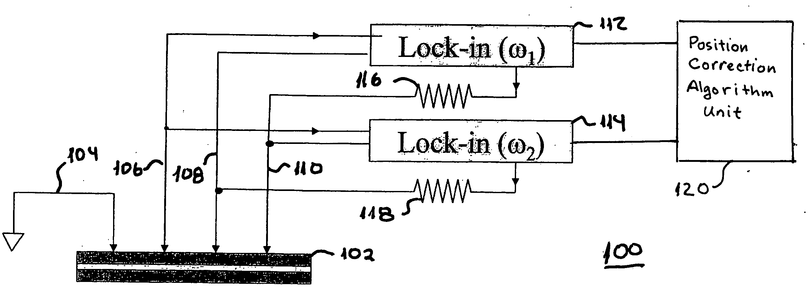
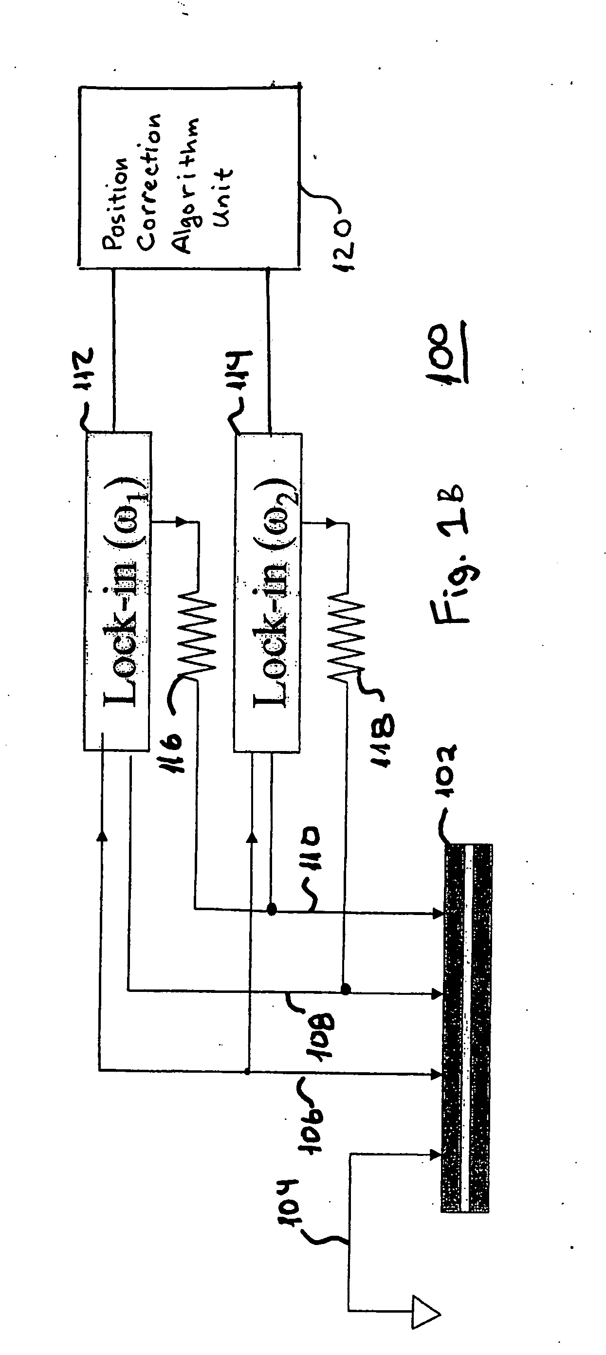
[0019] Referring now to FIG. 1B, a schematic of a measurement system 100 constructed in accordance with a preferred embodiment of the present invention is shown. The measurement system 100 is preferably used to measure a property such as the resistance per square or the magneto-resistance or areal resistance of a film stack 102. The embodiment of the system 100 shown inFIG. 1A utilizes four probes 104, 106, 108 and 110. Probe 104 provides a ground reference for the measurement system 100. Two lock-in circuits 112 and 114 are used to provide probe signals to the probes 108 and 110 and receive response signals from probes 106, 108 and 110. The first lock-in circuit 112 produces a first probe signal having a first frequency of ω1. Preferably, the first probe signal is a current signal. The first probe signal is provided from the lock-in circuit 112 to the probe 110 through a bias resistor 116. In response to the first probe signal, a corresponding voltage is created between probes 106 ...


PUM


Abstract

An improved method and apparatus for determining a property based upon at least two measurements uses simultaneous probe signals having two different frequencies. The probe signals are produced simultaneously such that the position of the probes is identical when the probe signals are produced. The responses to the two probe signals have frequencies that correspond to the probe signals. The individual responses are isolated from each other based upon their differing frequencies by frequency lock-in circuits. By performing the measurements simultaneously, positional errors that are introduced due to small changes that occur in the position of the probes if the measurements are taken sequentially are eliminated.

Description

CROSS-REFERENCE TO RELATED APPLICATIONS [0001] Not Applicable. STATEMENT REGARDING FEDERALLY SPONSORED-RESEARCH OR DEVELOPMENT [0002] Not Applicable. INCORPORATION BY REFERENCE OF MATERIAL SUBMITTED ON A COMPACT DISC [0003] Not Applicable. FIELD OF THE INVENTION [0004] The present invention broadly relates to the field of precision measuring devices. More particularly, the present invention relates to the use of simultaneous probe signals having different frequencies to allow for the cancellation of time-dependent errors that are introduced by small changes in the position of the probes used to take the measurements when the probe signals are produced sequentially. BACKGROUND OF THE INVENTION [0005] Probes for measuring resistivity in sheets and wafers are known in the art. One example of such probes is the four-point probe as shown in FIG. 1A. The purpose of a 4-point probe is to measure the resistivity of a semiconductor material. It can measure either bulk or thin film specimens....

Claims


Application Information

Patent Timeline
IPC IPC(8): G01R27/14G01R31/26
CPCG01R31/2648G01R27/14
Inventor ABRAHAM, DAVID WILLIAMWORLEDGE, DANIEL
Owner IBM CORP
Why Eureka
Try Eureka