Ac signal level detection circuit
a detection circuit and signal level technology, applied in the direction of ac-dc conversion, measurement, pulse technique, etc., can solve the problems of difficult to detect peak voltage, unrealistic budgeting, and difficult to secure the area on the ic that allows capacitance of 100, so as to improve reliability and low cost
- Summary
- Abstract
- Description
- Claims
- Application Information
AI Technical Summary
Benefits of technology
Problems solved by technology
Method used
Image

Examples
first embodiment
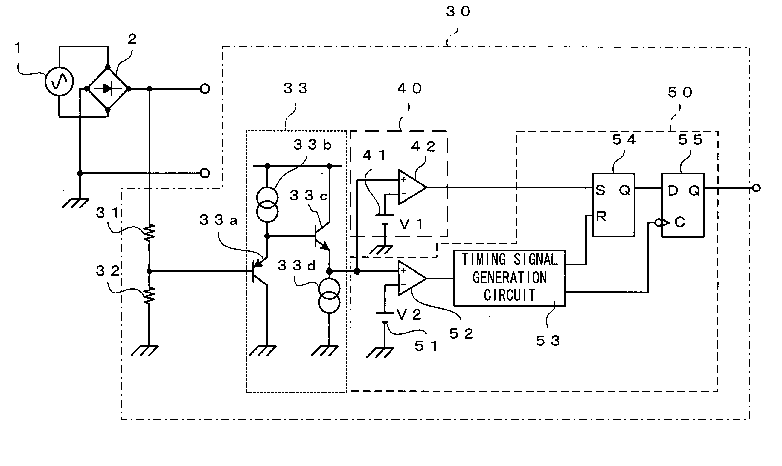
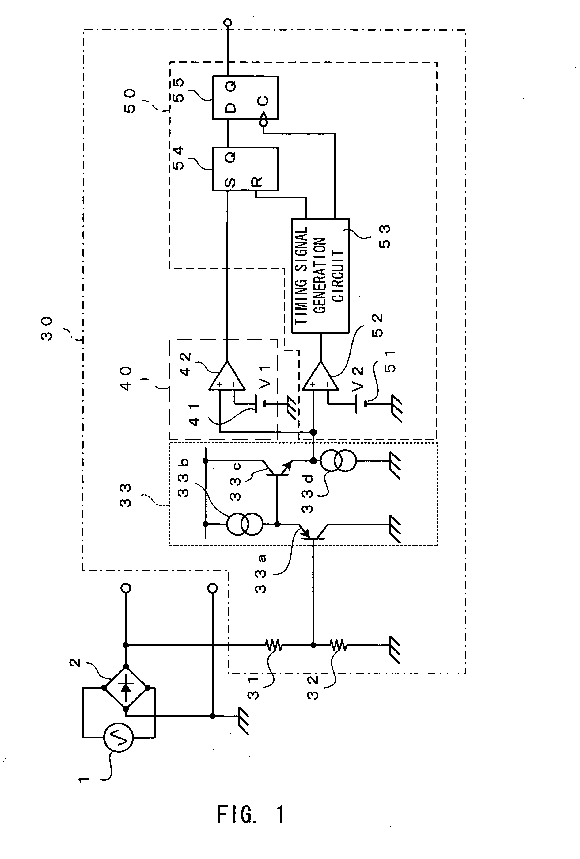
[0066]FIG. 1 is a configuration diagram showing an AC voltage detection circuit according to the first embodiment of the present invention.
[0067] This AC voltage detection circuit 30 is a circuit which detects a power source voltage supplied from an AC power source 1 to an unillustrated power unit and generates a determination signal identifiably representing whether the power source voltage is 100 volts or 200 volts.
[0068] The AC voltage detection circuit 30 comprises voltage division resistors 31 and 32 connected to a full-wave rectifying circuit 2, an internal regulator 33, a comparator / detector 40, and a determination signal generator 50.
[0069] The full-wave rectifying circuit 2 is connected to the AC power source 1 and supplies a rectified voltage to the power unit. The resistor 31 and the resistor 32 are connected in series between the positive electrode of the full-wave rectifying circuit 2 and the ground. The connection node of the resistor 31 and resistor 32 is connected...
second embodiment
[0093]FIG. 4 is a diagram showing an example of configuration of an AC voltage detection circuit according to the second embodiment of the present invention.
[0094] This AC voltage detection circuit 30A comprises voltage division resistors 61 and 62 connected to a full-wave rectifying circuit 2, an internal regulator 63, a comparator / detector 70, and a determination signal generator 80.
[0095] The resistor 61 and resistor 62 correspond to the resistors 31 and 32 of the first embodiment, and are connected in series between the positive electrode of the full-wave rectifying circuit 2 and the ground. The internal regulator 63 corresponds to the internal regulator 33 of the first embodiment, and the connection node of the resistor 61 and resistor 62 is connected to the base of a PNP type transistor 63 in the internal regulator 63.
[0096] The corrector of the transistor 63a is connected to the ground, and the emitter of the transistor 63a is connected to a power source wiring via a const...
third embodiment
[0116]FIG. 7 is a diagram showing an example of configuration of an AC voltage detection circuit according to the third embodiment of the present invention, where components common to the components of the second embodiment shown in FIG. 4 are give the same reference numerals.
[0117] This AC voltage detection circuit 30B is obtained by replacing the comparator / detector 70 and determination signal generation unit 80 in the AC voltage detection circuit of the second embodiment with a comparator / detector 90 and determination signal generation unit 100 shown in FIG. 7. The other components are the same as the second embodiment.
[0118] The comparator / detector 90 comprises a power source 91 and a comparator 72. The power source 91 generates a reference voltage lower than a reference voltage V1, when the rectified voltage generated by the internal regulator 63 rises and the output of the comparator 72 changes from “L” to “H”. The power source 91 changes the reference voltage that has been ...
PUM
 Abstract
Description
Claims
Application Information
 - R&D
- Intellectual Property
- Life Sciences
- Materials
- Tech Scout
- Unparalleled Data Quality
- Higher Quality Content
- 60% Fewer Hallucinations
Browse by: Latest US Patents, China's latest patents, Technical Efficacy Thesaurus, Application Domain, Technology Topic, Popular Technical Reports.
© 2025 PatSnap. All rights reserved.Legal|Privacy policy|Modern Slavery Act Transparency Statement|Sitemap|About US| Contact US: help@patsnap.com