System, method, and apparatus for remotely monitoring the status of a machine

Inactive Publication Date: 2005-07-14
MOU DAVID WEI HUA
View PDF24 Cites 21 Cited by
  • Summary
  • Abstract
  • Description
  • Claims
  • Application Information

AI Technical Summary

Benefits of technology

[0012] It is a second objective of the invention to provide a system, method, and apparatus for remotely monitoring existing machines with no built-in communications capabilities, and without having to modify the machines to include such capabilities.
[0013] It is a third objective of the invention to prov

Problems solved by technology

None of the prior systems, methods, or devices for remotely

Method used


Image

  • System, method, and apparatus for remotely monitoring the status of a machine
  • System, method, and apparatus for remotely monitoring the status of a machine
  • System, method, and apparatus for remotely monitoring the status of a machine

Examples


Embodiment Construction

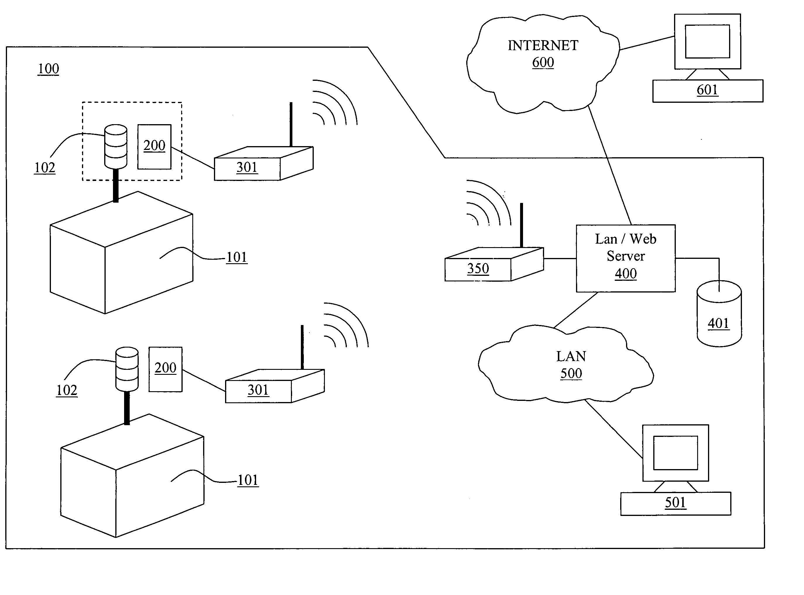
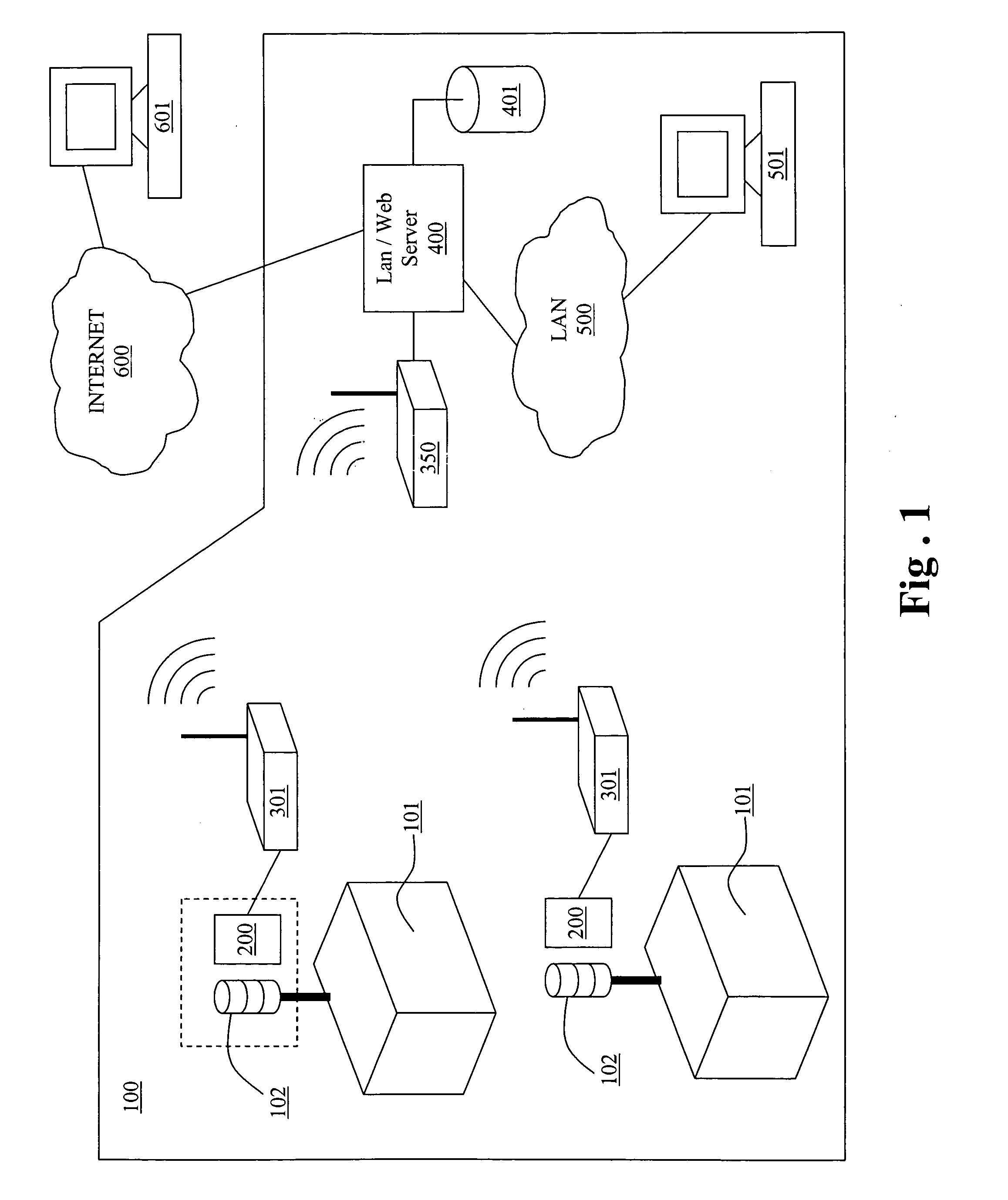
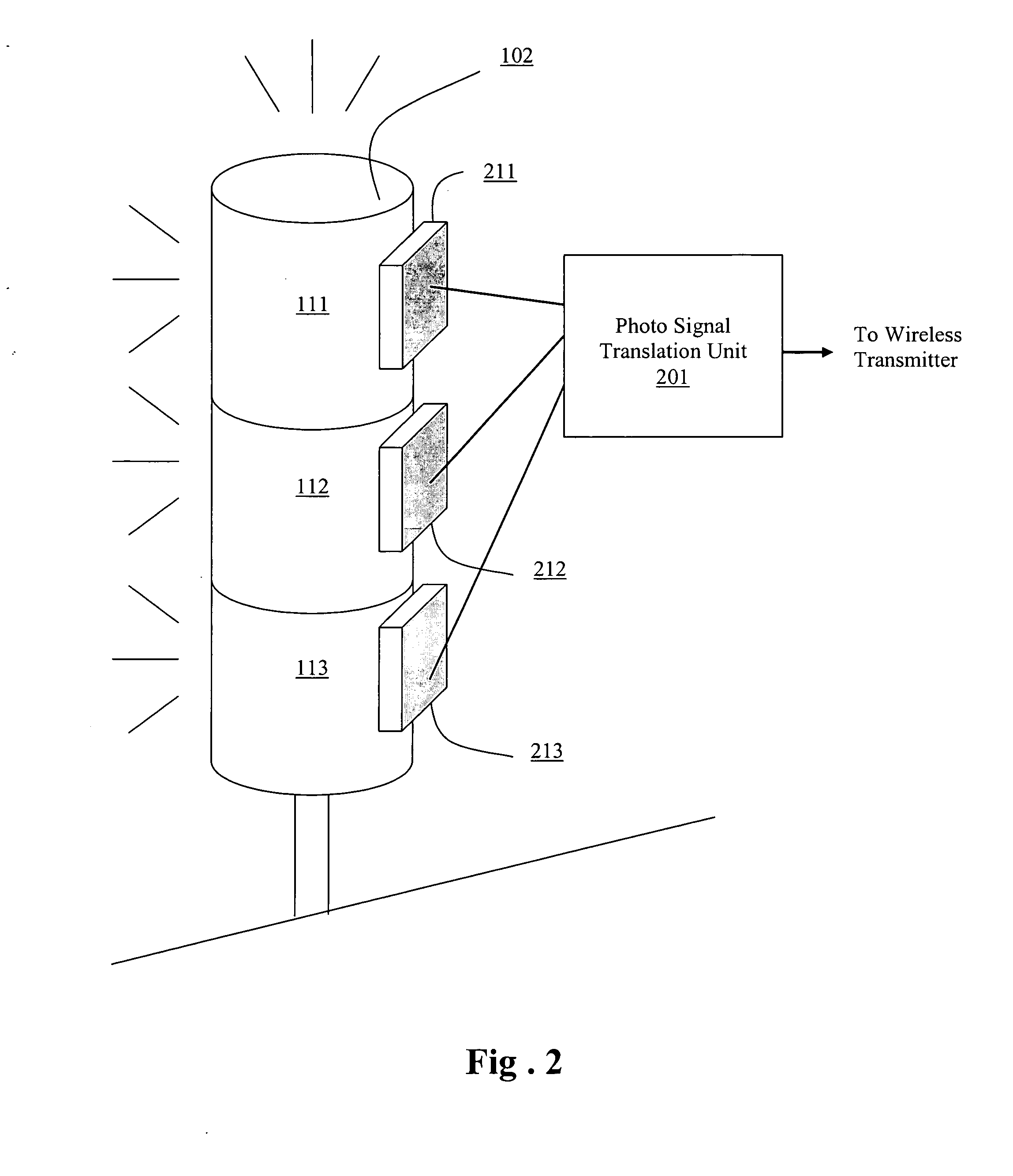
[0032] As illustrated in FIG. 1, a machine monitoring system constructed in accordance with the principles of a preferred embodiment of the invention includes at least one machine 101 to be monitored. Machine 101 may, by way of example and not limitation, be one of a plurality of machines on the floor of a machine shop, factory, office, or other facility 100, and must include at least one status indicator light 102. Machine 101 may be any type of machine, device, instrument, equipment, or the like having at least one status light.

[0033] The status indicator light is monitored by a photo sensing unit 200 connected to or including a wireless transmitter 301. Also situated in the machine shop, factor, office, or other facility 100 is a receiver 350 capable of receiving signals from, at least, one transmitter 301. Preferably, receiver 350 is capable of receiving signals from a plurality of transmitters 301 to enable monitoring of multiple machines.

[0034] Receiver 350 may be directly c...


PUM


Abstract

A system, method, and apparatus of remotely monitoring a status of a machine monitors machine status based on light emitted by a machine status indicator light on the machine. The light is detected by a photosensor and converted into signals for transmission to a remote receiver, network server, or other monitoring device.

Description

BACKGROUND OF THE INVENTION [0001] 1. Field of the Invention [0002] This invention relates to a system, method, and apparatus for remotely monitoring the status of a machine, instrument, or device (hereinafter referred to collectively as a “machine”), and in particular to a system, method, and apparatus which remotely monitors the status of the machine by detecting indicator lights on the machine. The system, method, and apparatus of the invention can be used to monitor the status of any machine or other device having a status indicator light, without having to modify the machine, using a simple and inexpensive photosensor unit having wired or wireless remote communication capabilities. [0003] 2. Description of Related Art [0004] Virtually all machines need to be monitored for proper operation. To facilitate monitoring, most machines are equipped with indicator lights that indicate the status of various machine functions, or that indicate malfunctions or conditions requiring attenti...

Claims


Application Information

Patent Timeline
IPC IPC(8): G08B5/22G08B5/36
CPCG08B5/22
Inventor MOU, DAVID WEI HUA
Owner MOU DAVID WEI HUA
Why Eureka
Try Eureka