
Liquid level detection method and apparatus

a liquid level and detection method technology, applied in liquid/fluent solid measurement, machines/engines, instruments, etc., can solve the problems of adding extra weight to the printer carriage, and affecting the use of the printer, etc., to achieve the effect of simple structure and reliable us

Inactive Publication Date: 2005-07-14
EASTMAN KODAK CO
View PDF29 Cites 80 Cited by
  • Summary
  • Abstract
  • Description
  • Claims
  • Application Information

AI Technical Summary

Benefits of technology

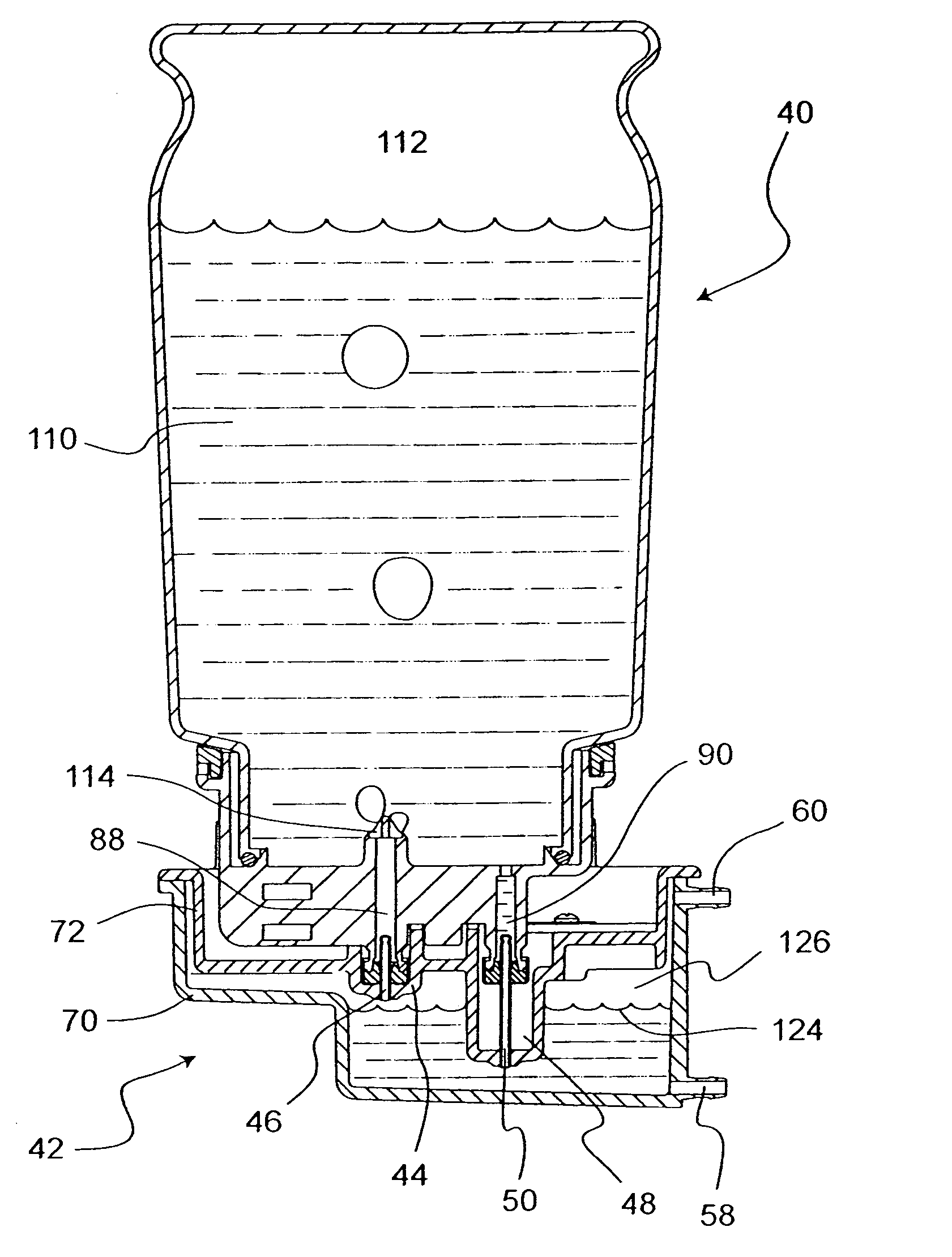
[0012] It is therefore an object of the invention to provide an ink presence sensing system that is simple in structure and reliable in use. More importantly, the sensing system should generate binary output signal to discriminate the ink presence state from the no ink presence state.
[0014] According to another aspect of the invention, the light detector is placed proximate to the second wall section to receive the light from the light emitter when ink is not present in the reservoir at the predetermined level. The embodiment has the advantage of detecting opaque and reflective inks.

Problems solved by technology

Failure of a disposable print cartridge is usually related to electrical damages to the resistors used to vaporize the ink and eject droplets from the nozzles.
But this approach adds extra weight on the printer carriage, which moves side to side continuously across the media width for image printing.
The extra weight on the carriage causes more mechanical stress to the printer structure and demands a larger motor to drive the carriage.
Running out of ink may result in catastrophic print cartridge failure due to cartridge running dry or image printing failure due to ink starvation.
Such a sensing system may not be universal to all liquids.
For example, a reflective liquid may cause malfunction of sensing.

Method used


Image

  • Liquid level detection method and apparatus
  • Liquid level detection method and apparatus
  • Liquid level detection method and apparatus

Examples


Embodiment Construction

[0041] The present description will be directed in particular to elements forming part of, or cooperating more directly with, apparatus and methods in accordance with the present invention. It is to be understood that elements not specifically shown or described may take various forms well known to those skilled in the art.

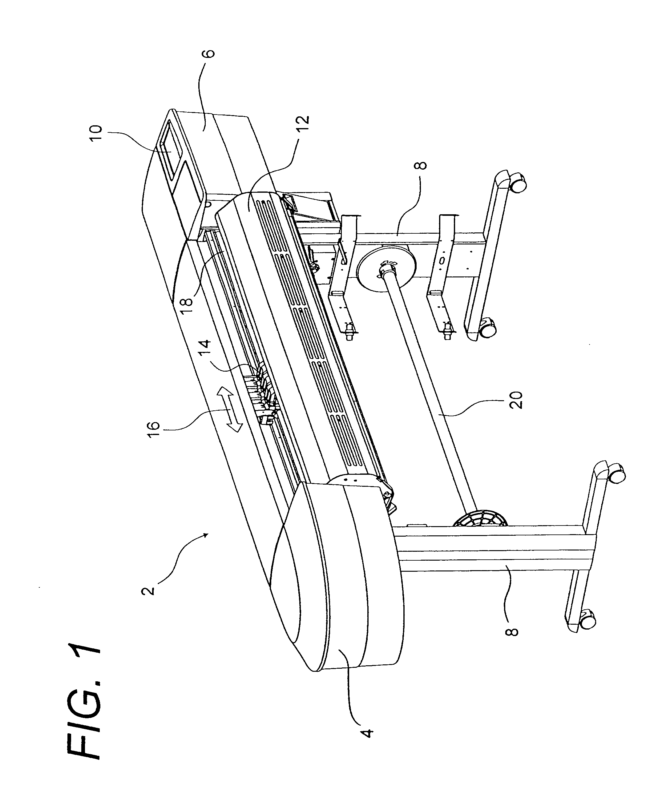
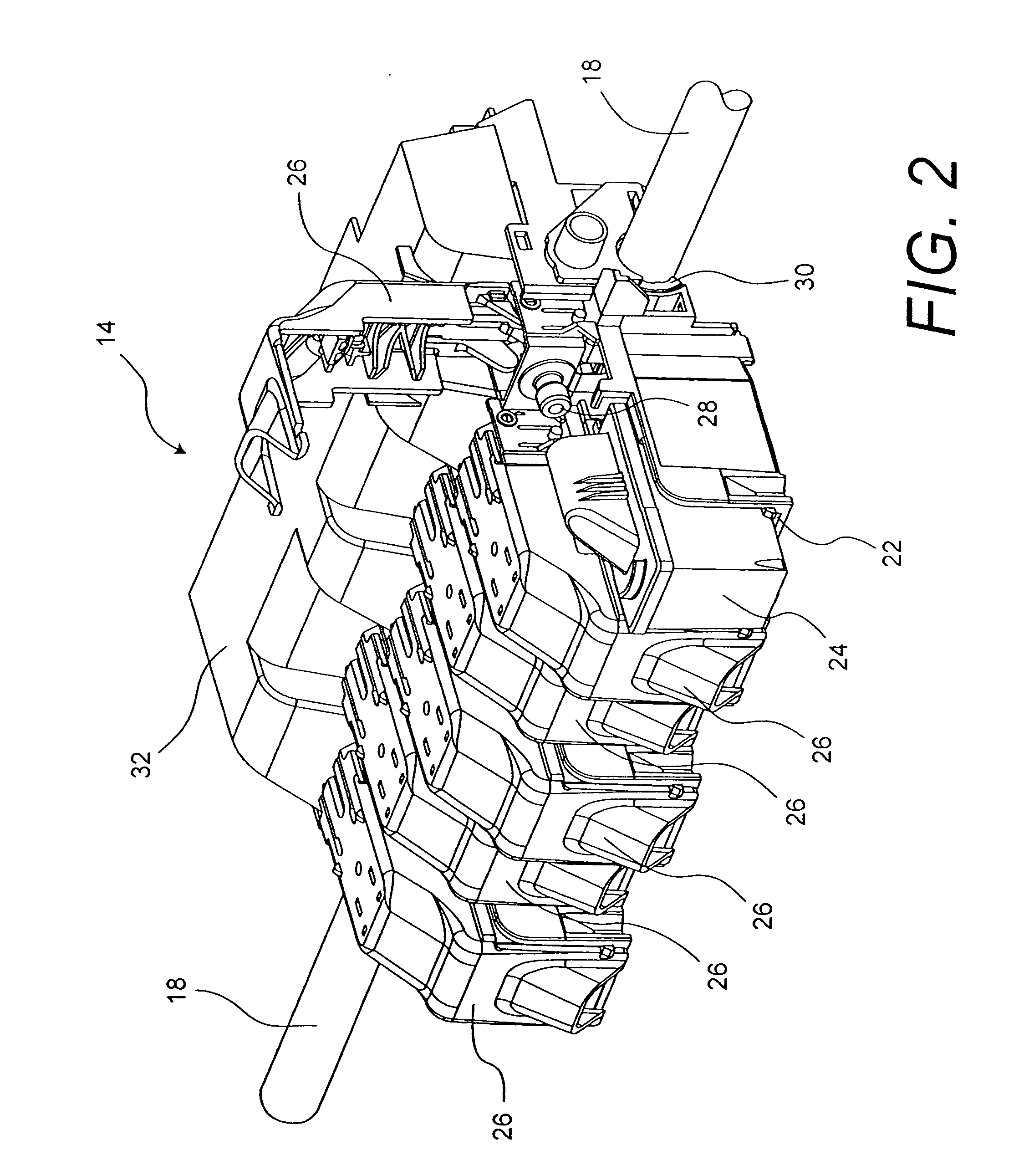
[0042] Referring to FIG. 1, an example of a wide format inkjet printer 2 is shown including a left side housing 4 and a right side housing 6, and is supported by a pair of legs 8. A wide format, or large format, inkjet printer is typically floor standing. It is capable of printing on media larger than A2 or wider than 17″. In contrast, a desk-top, or small format, printer typically prints on media sized 8.5″ by 11″ or 11″ by 17″, or the metric standard A4 or A3. The right side housing 6 shown in FIG. 1 has a display with keypad 10 on top for operator input and control, and encloses various electrical and mechanical components, including the main electronic board ...


PUM


Abstract

A sensing system is described for detecting the presence of ink at a predetermined level in an ink reservoir for an ink jet printer. The reservoir includes a perimetric wall having first and second wall sections, wherein at least a portion of said first wall section and a portion of the second wall section are substantially transmissive to light. A light emitter is located proximate to the first wall section and positioned at the predetermined level. A photo detector is positioned at the predetermined level and located proximate to the second wall section for detecting the light emitted from the light emitter, the light emitter being oriented to direct light at the photodetector. The light from the light emitter follows a first path when ink is present in the reservoir at the predetermined level and follows a second path when ink is not present in the reservoir at the predetermined level, the photodetector receiving the light from the light emitter traveling only one of the first path or the second path.

Description

CROSS REFERENCE TO RELATED APPLICATIONS [0001] This is a 111A application of Provisional Application Ser. No. 60 / 534,877, Filed Jan. 8, 2004, entitled LIQUID LEVEL DETECTION METHOD AND APPARATUS by Timothy T. Grady, et al.FIELD OF THE INVENTION [0002] The present invention relates generally to detecting the presence of liquid at a predetermined level in a liquid reservoir, and more particularly to detecting the presence of ink at a predetermined level in an ink reservoir for an ink jet printer. BACKGROUND OF THE INVENTION [0003] Inkjet type printers typically employ a print cartridge that is moved in a transverse fashion across a print media. Contemporary disposable inkjet print cartridges typically include a self-contained ink container, a print head including a plurality of inkjet nozzles in combination with the ink container, and a plurality of external electrical contacts for connecting the inkjet nozzles to driver circuitry in the printer. Failure of a disposable print cartridg...

Claims


Application Information

Patent Timeline
IPC IPC(8): B41J2/175G01F23/292
CPCB41J2/17509B41J2/17513B41J2/1752G01F23/2922B41J2/17553B41J2/17566B41J2002/17573B41J2/17523
Inventor GRADY, TIMOTHY T.PAN, YICHUAN
Owner EASTMAN KODAK CO
Learn More