
Color filter and liquid crystal display using the same

Inactive Publication Date: 2005-07-14
INNOLUX CORP
View PDF0 Cites 5 Cited by
  • Summary
  • Abstract
  • Description
  • Claims
  • Application Information

AI Technical Summary

Benefits of technology

[0011] An object of the present invention is to provide a color filter which has reduced or no hue diversity.
[0015] The alternating arrangement of the transmission sections and the reflection sections of the pixels can eliminate the strip-shaped hue diversity of the prior art, and can provide a uniform pattern of hue balance over the whole display area. Furthermore, in various sub-embodiments of the present invention, different optical thicknesses of the transmission sections and the reflection sections (or color layers of the reflection sections) can make the lengths of all optical paths in the color filter uniform. This avoids the light intensity, contrast and saturation hue diversity of the prior art, and can provide uniform hue over the whole display area.

Problems solved by technology

This reduces the quality of the displayed image.
That is, the light intensity, contrast and saturation are not uniform.
This further reduces the quality of the displayed image.

Method used


Image

  • Color filter and liquid crystal display using the same
  • Color filter and liquid crystal display using the same
  • Color filter and liquid crystal display using the same

Examples


Embodiment Construction

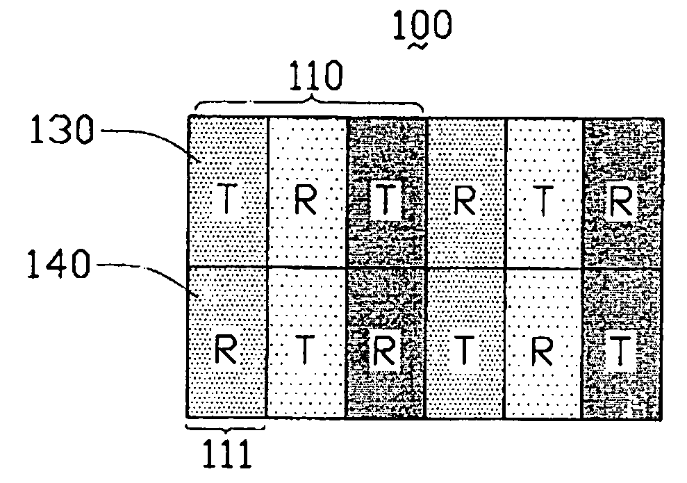
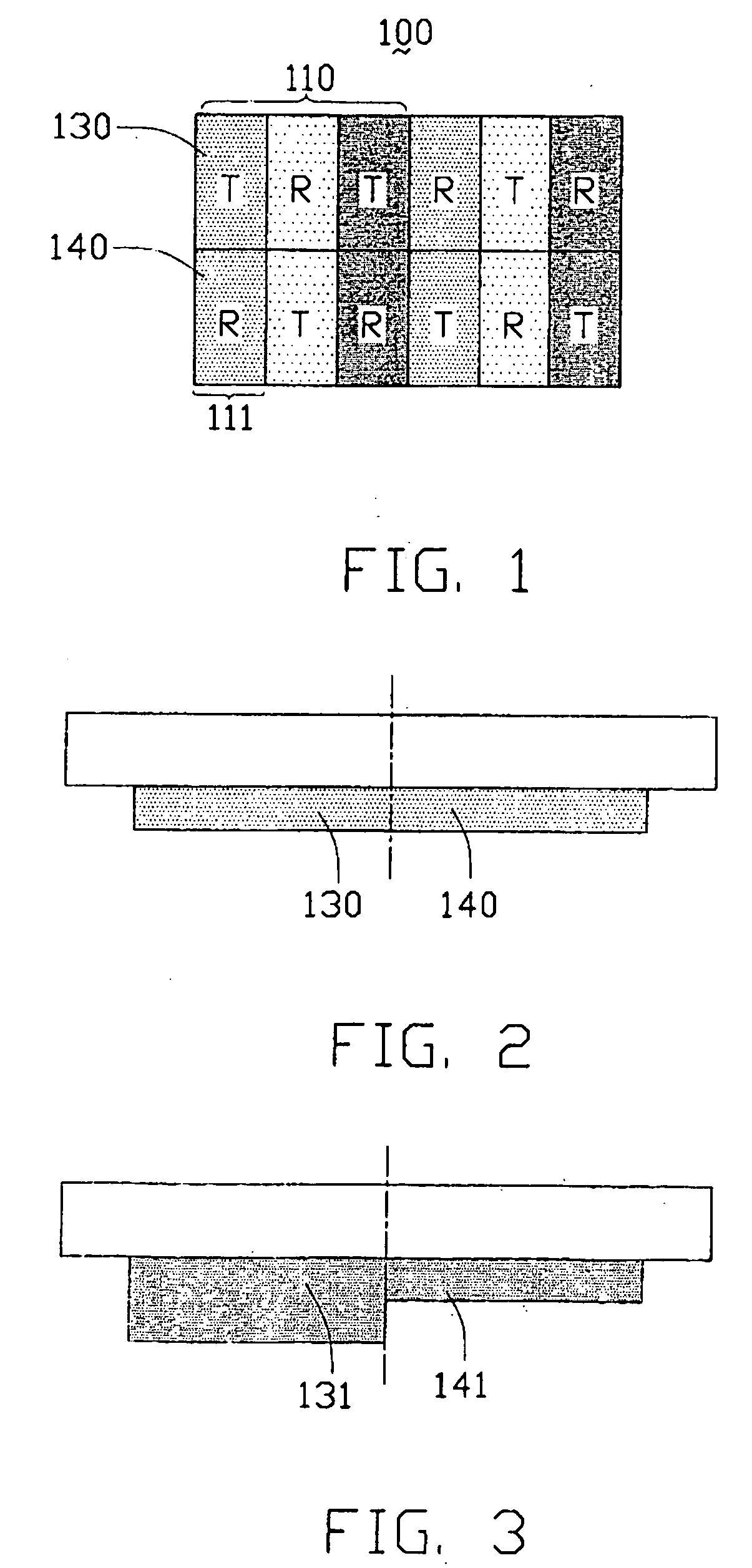
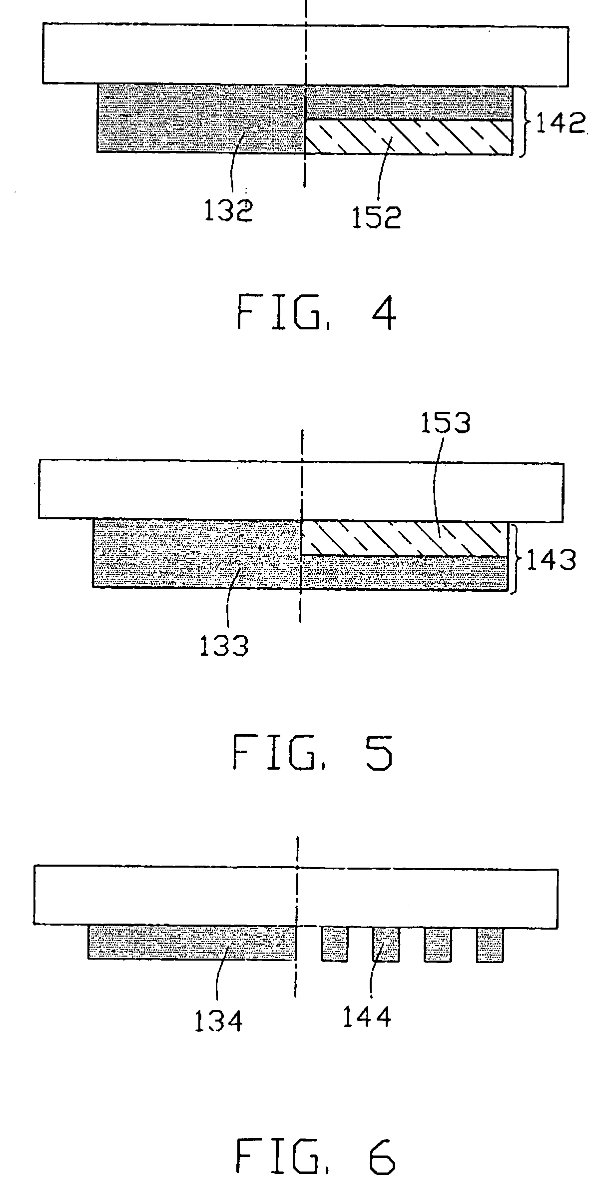
[0029] Referring to FIG. 1, two adjacent pixels 110 of a color filter 100 in accordance with the first preferred embodiment of the present invention are shown, the pixels 110 being in accordance with the first sub-embodiment of the present invention. The color filter 100 includes millions of the pixels 110 arranged in a regular, rectangular array of rows and columns. Each pixel 110 comprises three sub-pixels 111 of Red, Green and Blue pigment respectively. The sub-pixels 111 are arranged in a row. Each sub-pixel 111 comprises two sections arranged one above the other. Thus, each pixel 110 comprises an array of two rows and three columns of sections. Each section is either a transmission (“T”) section 130 or a reflection (“R”) section 140. In each pixel 110, the transmission sections 130 and the reflection sections 140 are alternately arranged along each row and along each column. Further, in the overall array of pixels 110, the transmission sections 130 and the reflection sections 1...


PUM


Abstract

A color filter (100) includes pixels (110), each pixel including three sub-pixels (111), and each sub-pixel including a reflection section (R) and a transmission section (T). In each pixel, the transmission sections and the reflection sections are alternately arranged along each row of the sections and along each column of the sections. The alternating arrangement of the transmission sections and the reflection sections of the pixels can provide a uniform pattern of hue balance over the whole display area. Furthermore, in various embodiments described, different optical thicknesses of the transmission sections and the reflection sections (or color layers of the reflection sections) can provide uniform hue over the whole display area.

Description

BACKGROUND OF THE INVENTION [0001] 1. Field of the Invention [0002] The present invention relates to color filters, and especially to color filters used in display devices such as liquid crystal display devices. [0003] 2. Description of the Prior Art [0004] Liquid crystal display devices have become very popular in recent years because of their advantages over display devices that utilize cathode ray tubes. In particular, liquid crystal display devices are thinner, and offer lower power consumption. [0005] Liquid crystal display devices are generally divided into three types according to the way in which they utilize available light: transmissive type, reflective type, and transflective type. [0006] A transflective liquid crystal display device has the functions of both a transmissive and a reflective liquid crystal display device, and has received much attention lately. The transflective liquid crystal display device reflects ambient light when it is used in a bright ambient enviro...

Claims


Application Information

Patent Timeline
IPC IPC(8): G02F1/1335
CPCG02F2203/09G02F1/133514
Inventor WU, MEI-LINGYEH, SHENG-SHIOUPANG, JIA-PANG
Owner INNOLUX CORP
Learn More