Method for detecting eccentricity of an optical disc, and optical disc drive that performs the method
- Summary
- Abstract
- Description
- Claims
- Application Information
AI Technical Summary
Benefits of technology
Problems solved by technology
Method used
Image
Examples
Embodiment Construction
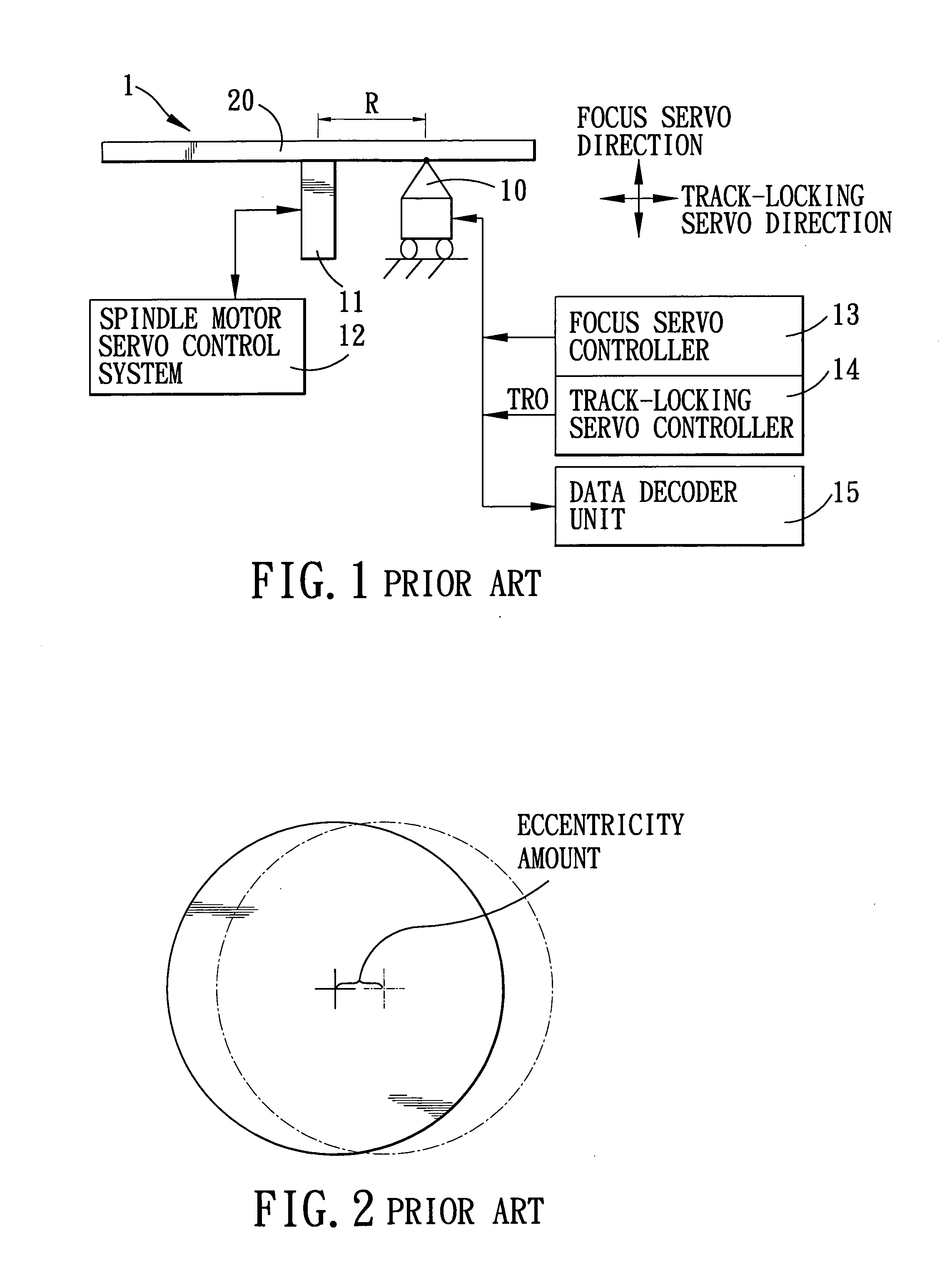
[0024]FIG. 1 is a schematic circuit block diagram to illustrate the general construction of an optical disc drive 1 that is applicable to the following preferred embodiments of the present invention. The optical disc drive 1 is shown to include a spindle motor 11 adapted for rotating an optical disc 20, a spindle motor servo control system 12 for controlling rotation of the spindle motor 11, an optical pickup head 10, a focus servo controller 13 for controlling focusing of the optical pickup head 10, a track-locking servo controller 14 for controlling track-locking of the optical pickup head 10, and a data decoder unit 15 for decoding data reproduced from the optical disc 20.
[0025] Referring to FIG. 2, when an eccentric optical disc is rotated by the optical disc drive, because of a shift in the center, the radii of recorded tracks vary continuously. Hence, focusing and track-locking during reproduction and recording of data on the eccentric optical disc are hard to control, which ...
PUM
 Abstract
Description
Claims
Application Information
 - R&D Engineer
- R&D Manager
- IP Professional
- Industry Leading Data Capabilities
- Powerful AI technology
- Patent DNA Extraction
Browse by: Latest US Patents, China's latest patents, Technical Efficacy Thesaurus, Application Domain, Technology Topic, Popular Technical Reports.
© 2024 PatSnap. All rights reserved.Legal|Privacy policy|Modern Slavery Act Transparency Statement|Sitemap|About US| Contact US: help@patsnap.com


