Modulation and transmission methods to provide a wireless link and transmitter circuit for providing a wireless link

Inactive Publication Date: 2005-07-14
LUCENT TECH INC
View PDF7 Cites 2 Cited by
  • Summary
  • Abstract
  • Description
  • Claims
  • Application Information

AI Technical Summary

Benefits of technology

[0011] The exemplary embodiments of the present invention provide a modulation method, transmission method, and transmitter circuit that may enable real

Problems solved by technology

These small millimeter waves make E-Band a challenging band to use.
Transmission range may be severely limited, and the signals can sometimes be blocked by rain, fog or even high humidity.
However, e

Method used


Image

  • Modulation and transmission methods to provide a wireless link and transmitter circuit for providing a wireless link
  • Modulation and transmission methods to provide a wireless link and transmitter circuit for providing a wireless link
  • Modulation and transmission methods to provide a wireless link and transmitter circuit for providing a wireless link

Examples


Embodiment Construction

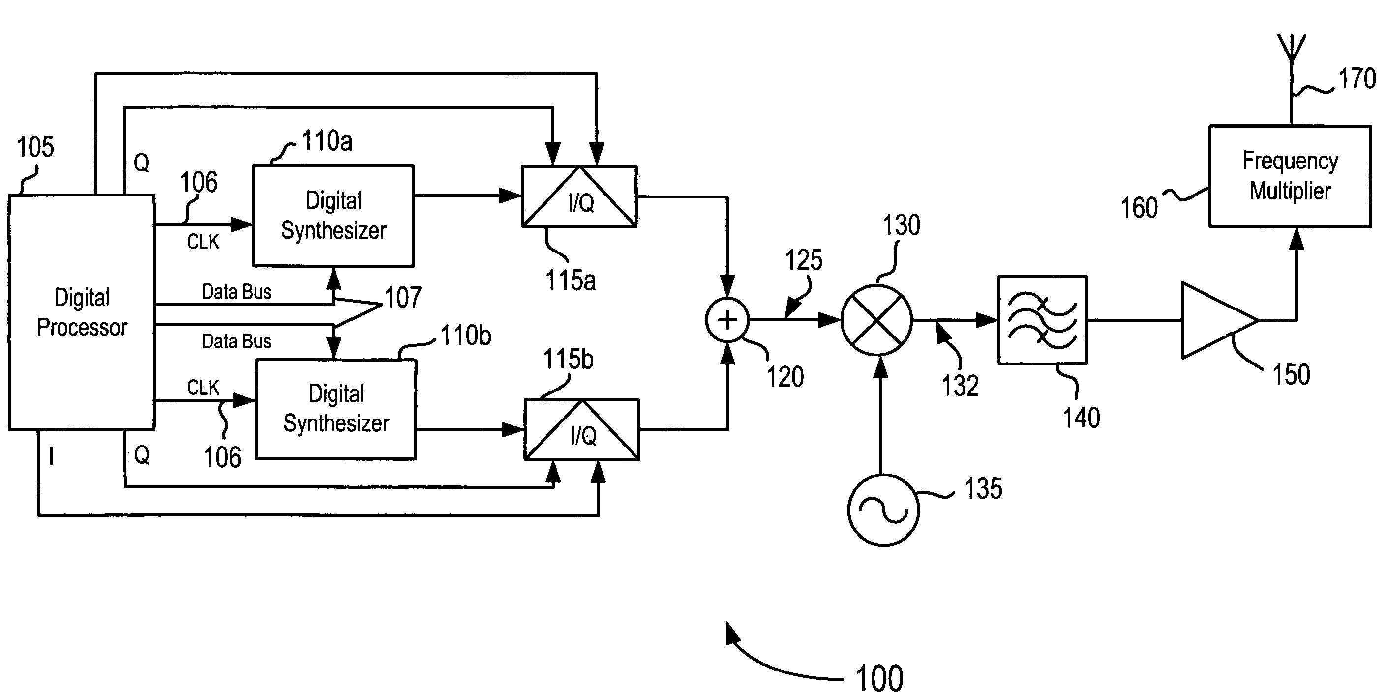
[0017] Although the following description relates to a wireless point-to-point or point-to-multipoint link envisioned as an alternative to a fiber optic link such as a T1 / E1 in wireless communication networks or systems based on as 802.11, CDMA (3G-1x EV-DO, 3G-1x EV-DV) and / or UMTS technologies, and will be described in this exemplary context, it should be noted that the exemplary embodiments shown and described herein are meant to be illustrative only and not limiting in any way. As such, various modifications will be apparent to those skilled in the art for application to wireless communication systems or networks based on technologies other than the above which may be in various stages of development and intended for future replacement of, or use with, the above networks or systems.

[0018] The exemplary embodiments of the present invention envision modifying an existing multifunctional transceiver, such as a multifunctional W-band transceiver used in the automotive radar market ...


PUM

PropertyMeasurementUnit
Frequencyaaaaaaaaaa
Frequencyaaaaaaaaaa
Frequencyaaaaaaaaaa

Abstract

A modulation method, transmission method, and transmitter circuit are described which may enable realization of a wireless link for ultra-high transmission rates in the downlink to users. In a method of modulating an input signal to obtain a desired intermediate signal, the intermediate signal is to be processed for transmission over a wireless link at a carrier frequency within a desired frequency band. The processing may include subjecting the intermediate signal to a frequency multiplier operation that exhibits an ambiguous transfer function. In the modulation method, an input signal is provided, and a set of signal states applicable to the desired intermediate signal are generated so that a signal output from the frequency multiplier operation has a substantially non-ambiguous relation to the desired intermediate signal. The input signal may thus be modulated according to I and Q baseband signals to obtain the desired intermediate signal with the generated set of signal states.

Description

BACKGROUND OF THE INVENTION [0001] 1. Field of the Invention [0002] The present invention relates generally to wireless communication links. [0003] 2. Related Art [0004] On Oct. 16, 2003, the Federal Communications Commission (FCC) adopted service rules for commercial use of a previously empty swath of spectrum, in an effort to promote the development of an additional competitive broadband deployment platform. This domain lies in the frequency bands from 71 to 76 gigahertz (GHz), 81 to 86 GHz and 92 to 95 GHz—collectively known as the ‘E-Band’, the highest frequencies ever licensed by the FCC. This high-frequency swath of spectrum may eventually become essential to ultra-high-speed data communication to provide a broad range of innovative products and services, including high-speed, point-to-point (PTP) wireless local area networks and operations, and broadband internet access, for example. [0005] Broadcast television and radio, mobile phones, WiFi computer networks and other famili...

Claims


Application Information

Patent Timeline
IPC IPC(8): H03C3/00H04L27/18H03C3/02H04B1/04H04B7/26H04L27/00H04L27/10H04L27/36
CPCH04L27/367H03C3/02B01D39/08B01D46/52B01D46/0005B82Y30/00B01D46/66
Inventor BARAS, TORBENMETZ, CARSTEN
Owner LUCENT TECH INC
Why Eureka
Try Eureka