Sports equipment stick with truss construction

a technology of trusses and sticks, applied in the field of sticks, shafts and bats, to achieve the effect of enhancing the strength of the handle, reducing weight, and adding strength

Inactive Publication Date: 2005-07-14
RI HLDG
View PDF8 Cites 72 Cited by
  • Summary
  • Abstract
  • Description
  • Claims
  • Application Information

AI Technical Summary

Benefits of technology

[0012] The present invention reveals the next generation in sports shaft and stick technology. The instant design incorporates trusses and curved cutaway surfaces to add strength, reduce weight and provide aerodynamic airflow to sports sticks, and in particular to lacrosse sticks, is not revealed by the prior cited patents. The instant invention is designed with both concave and convex surfaces to enhance the strength of the handle in all directions. This concept utilized in the instant invention follows the design of an aircraft wing, where strength to weight ratio is extremely important.
[0013] The present invention utilizes the airfoil shape, typical in airplane wing and fuselage design, to create a superior stick profile in regard to airflow considerations. By incorporating this airfoil concept into material cutaways manufactured in a truss-like structure, through either the whole or some portion of the stick, the resultant combination of the aerodynamic advantages and the strength inherent in the curved truss surfaces, provides a drastically upgraded sport stick. Further, incorporating modern material considerations into the instant design only serves to render a lighter, stronger stick.
[0014] It is an object of the present invention to provide a multi-application sports stick or shaft that exhibits superior durability. It is an object of the present invention to provide a multi-application sports stick or shaft that exhibits the feel and handling capabilities of a lightweight shaft at heavier weights, due to the airfoil design.

Problems solved by technology

Further, incorporating modern material considerations into the instant design only serves to render a lighter, stronger stick.

Method used


Image

  • Sports equipment stick with truss construction
  • Sports equipment stick with truss construction
  • Sports equipment stick with truss construction

Examples


Embodiment Construction

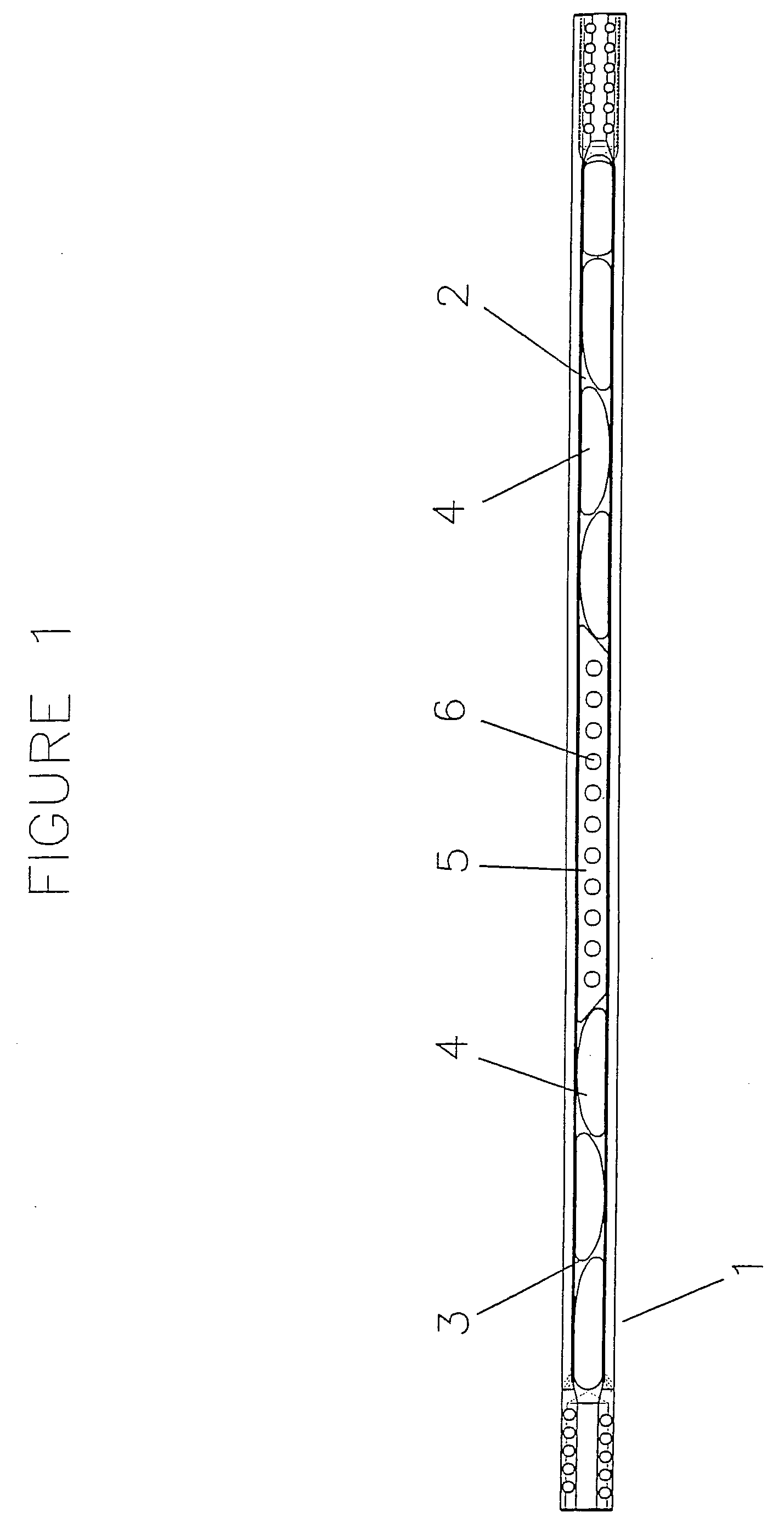
[0044] Referring now to FIG. 1, there is shown a stick construction comprising a shaft 1 equipped with three areas possessing cutaways or cavities. Further shown in divided segments are the upper region 2 and lower two region 3. Each of these regions containing series of airfoil shaped cavities 4. Positioned between the upper and lower regions is a central region 5, containing circular shaped cavities 6.

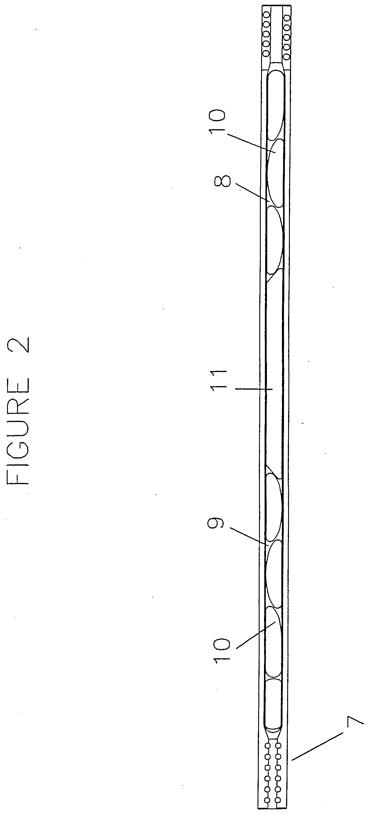
[0045] Referring next to FIG. 2, there is shown a stick construction comprising a shaft 7 equipped with three areas possessing cutaways or cavities. Further shown in divided segments are the upper region 8 and lower two region 9. Each of these regions containing series of airfoil shaped cavities 10. Positioned between the upper and lower regions is a solid central region 11. Further embodiments can include a shaft containing airfoil shaped hole through the entirety of the length.

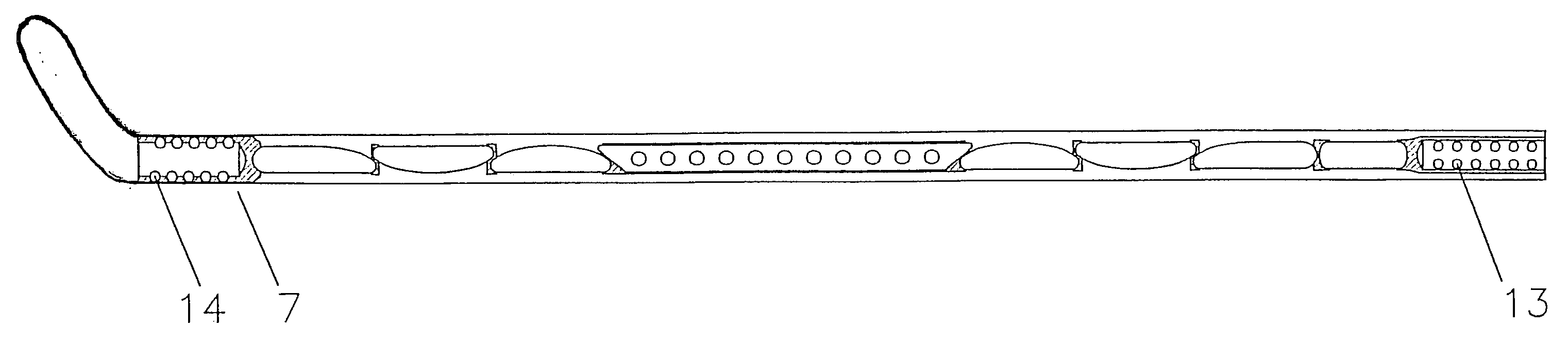
[0046] Referring to FIG. 3, there is shown a shaft 7 equipped with the grooved gripping area 12 extendin...


PUM


Abstract

A sports stick exhibiting a superior strength to weight ratio. The sports stick design allows for decreased flexure, increased rigidity and increased durability, which lend to greater generation of force, accuracy, reliability and longer life expectancy. The sports stick utilizes aerodynamic features in order to achieve an exposed truss like structure which permits airflow through the internal sections of the shaft which creates greater shaft acceleration and velocity. The sports stick also affords enhanced strength in the direction of a shot and receipt of a pass. The sports stick also provides for channeling away of fluids throughout the length of the stick. The sports stick also provides a system wherein weight can be regulated in multiple regions throughout by utilizing removable or fixed weighted elements or by sizing of cutaways strategically designed to be placed in a certain area of the stick, depending on player handling preference.

Description

FIELD OF THE INVENTION [0001] The present invention relates generally to sporting goods, namely sticks, shafts and bats for sports such as hockey, lacrosse, field hockey, golf, baseball, softball, polo and fishing. BACKGROUND OF INVENTION [0002] As designs of sports shafts, stick and handles have evolved from basic wooden structures lacking uniformity as to quality, strength, weight, and susceptibility to failure by fracturing. Many prior inventions have proposed the use of shafts or sticks comprising composites featuring plastic outer surfaces with inner cores of wood or aluminum. Further, as pointed out by prior inventions, many attempts have been made to utilize metallic material in the manufacture of sticks. [0003] The utility patent U.S. Pat. No. 3,473,806 issued to Patterson, discloses a lacrosse stick with a frame composed of reinforced plastic material with a much lighter material inserted into its core. Although a lightweight stick may results from this design, the requisit...

Claims


Application Information

Patent Timeline
Patent Type & Authority Applications(United States)
IPC IPC(8): A63B53/10A63B53/12A63B59/00A63B59/02
CPCA63B49/06A63B53/10A63B53/12A63B2243/005A63B59/0088A63B59/02A63B2225/01A63B59/0014A63B60/52A63B60/10A63B2102/14A63B60/06A63B59/20A63B60/08A63B60/50A63B2209/00A63B2209/02A63B60/00B21K17/00A63B60/006
Inventor RIGOLI, MICHAEL
Owner RI HLDG
Why Eureka
Try Eureka