Spinal nucleus replacement implants and methods

a technology of spinal nucleus and implants, which is applied in the field of spinal nucleus replacement implants and methods, can solve the problems of affecting the function of the spinal nucleus, so as to facilitate effective implantation and use, facilitate positioning, and improve the range of motion

Inactive Publication Date: 2005-07-14
SDGI HLDG
View PDF99 Cites 279 Cited by
  • Summary
  • Abstract
  • Description
  • Claims
  • Application Information

AI Technical Summary

Benefits of technology

[0008] One object of the present invention is to provide nucleus pulposus implants that better accommodate the disc nucleus space, that have an improved

Problems solved by technology

Intervertebral discs may be displaced or damaged due to trauma or disease.
The extruded nucleus pulposus may press on a spinal nerve, which may result in nerve damage, pain, numbness, muscle weakness and paralysis.
Intervertebral discs may also deteriorate due to the normal aging process.
As a disc dehydrates and hardens, the disc space height will be reduced, leading to instability of the spine, decreased mobility and pain.
The removal of the damaged or unhealthy disc may allow the disc space to collapse, which would lead to instability of the spine, abnormal joint mechanics, nerve damage, as well as severe pain.
Even though a certain degree of

Method used


Image

  • Spinal nucleus replacement implants and methods
  • Spinal nucleus replacement implants and methods
  • Spinal nucleus replacement implants and methods

Examples


example 1

[0080] Porous upper and lower surface layers 611a and 611b are 1 mm thick (no elastomeric material) and are provided on an intervertebral disc nucleus implant 610 shown in FIG. 61. The transition zone 612 right below the porous layers 611a and 611b continues throughout the implant and is between 4 mm and 12 mm thick (elastomeric material embedded in porous material). There is no center layer containing only elastomeric material. The overall implant height or thickness is between 6 mm and 14 mm.

example 2

[0081] Porous upper and lower surface layers 621a and 621b are 2 mm thick (no elastomeric material) and are provided on an intervertebral disc nucleus implant 620 shown in FIG. 62. The transition zones 622a and 622b right below the porous layers 621a and 621b are 2 mm thick (elastomeric material embedded in porous material). The middle layer 623 is 1 mm to 10 mm thick, and contains only elastomeric material. The overall implant height or thickness is 9 mm to 18 mm.

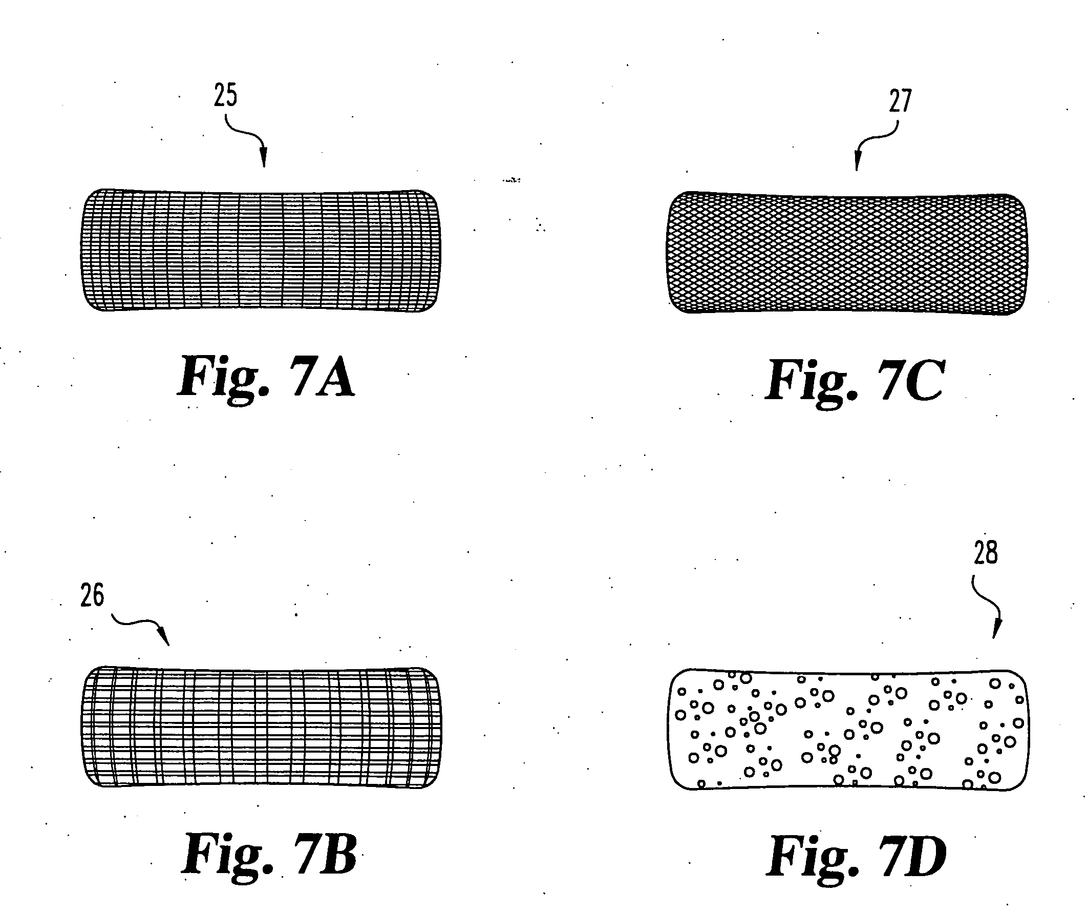
[0082] It is to be appreciated that the porous fabric or mesh can be made of a polymeric, metallic or ceramic material or combinations thereof. The porous fabric or mesh can be flexible / compressible, semi-flexible / semi-compressible, or rigid. The mean pore size of the porous surface may be between 50 microns to 2000 microns, and is preferably between 100 microns and 1000 microns for good bony or soft tissue ingrowth.

[0083] In certain forms of the invention, the implant may include only elastic body 15 having one or more ...


PUM

PropertyMeasurementUnit
Electrical resistanceaaaaaaaaaa
Surfaceaaaaaaaaaa
Circumferenceaaaaaaaaaa

Abstract

Improved nucleus pulposus implants are provided to better accommodate the disc nucleus space, to provide a modified compressive modulus, to facilitate positioning, to enhance fixation, and to facilitate effective implantation and use. Some implants have sloped upper and/or lower surfaces to provide a “wedge-shaped” implant, while other implants have circumferential grooves, and/or have radiographic markers, and/or are modified by including a material having a compression profile that differs from the compression profile of the predominant material of the implant. Some implants have surface features to enhance fixation to surrounding surfaces.

Description

CROSS-REFERENCE TO RELATED APPLICATIONS [0001] This application is a continuation-in-part of U.S. patent application Ser. No. 09 / 943,441, filed Aug. 30, 2001, which is a continuation-in-part of U.S. patent application Ser. No. 09 / 650,525, filed Aug. 30, 2000 and issued Sep. 16, 2003 as U.S. Pat. No. 6,620,196. This application is also a continuation-in-part of U.S. patent application Ser. No. 10 / 253,453, filed Sep. 24, 2002, which is a divisional application claiming priority from U.S. patent application Ser. No. 09 / 650,525, referenced above. This application is also a continuation-in-part of U.S. patent application Ser. No. 10 / 717,687, filed Nov. 20, 2003, which is a continuation-in-part of U.S. patent application Ser. No. 09 / 943,441, referenced above, and of U.S. patent application Ser. No. 10 / 459,630, which is also a continuation-in-part of U.S. patent application Ser. No. 09 / 650,525, referenced above. All of said priority applications are hereby incorporated herein by reference ...

Claims


Application Information

Patent Timeline
IPC IPC(8): A61B17/02A61B17/56A61F2/00A61F2/02A61F2/28A61F2/30A61F2/44A61F2/46A61L27/00
CPCA61B2017/0256A61F2230/0091A61F2/441A61F2/442A61F2/4611A61F2002/2817A61F2002/30062A61F2002/30092A61F2002/30133A61F2002/30179A61F2002/302A61F2002/30224A61F2002/30291A61F2002/30563A61F2002/30596A61F2002/30604A61F2002/30677A61F2002/30838A61F2002/30891A61F2002/30906A61F2002/30909A61F2002/30925A61F2002/30957A61F2002/4415A61F2002/444A61F2002/4495A61F2002/4627A61F2210/0004A61F2210/0014A61F2230/0015A61F2230/0058A61F2230/0065A61F2230/0069A61F2/30965A61F2002/30594
Inventor TRIEU, HAL H.
Owner SDGI HLDG
Why Eureka
Try Eureka