Prosthetic knee mechanism

a technology of prosthetic knees and knee joints, applied in the field of prosthetic knees, can solve the problems of difficult duplicate of human leg aspects, limbs that do not create the real movement of human limbs, and the designers of prosthetic knees have faced very difficult challenges, so as to and increase stance phase stability

Inactive Publication Date: 2005-07-14
BASSETT DAVID
View PDF14 Cites 31 Cited by
  • Summary
  • Abstract
  • Description
  • Claims
  • Application Information

AI Technical Summary

Benefits of technology

[0030] It is, therefore, an advantage of the present invention to provide a prosthetic knee mechanism for use by a individual that may provide stability.
[0031] Another advantage of the present invention is to provide a prosthetic knee mechanism that may use a mechanical braking mechanism.
[0032] Yet another advantage of the present invention is to provide a prosthetic knee mechanism that may use a mechanical braking mechanism to increase stance phase stability in a polycentric knee.
[0033] And, another advantage of the present invention is to provide a prosthetic knee mechanism that may use a mechanical braking mechanism to increase stance phase stability in a polycentric knee wherein the knee me...

Problems solved by technology

It is, of course, generally known that prosthetic knee designers have faced very difficult challenges when designing a limb for a user that may have lost one.
However, these limbs did not create the realistic movement of the human limb such as the legs.
Specifically, the one aspect of the human leg that has been so difficult to duplicate is the human knee.
However, even modern knee designers have found it difficult to create a mechanism that will simulate the function of the human knee.
The problem exists to create a mechanism that will bend effortlessly when desired by the user yet maintain the stability when it is needed in the absence of the musculature that aids the function in the normal human knee.
U.S. Pat. No. 3,863,274 illustrates a design that has a single axis but fails in its ability to allow unrestricted flexion of the knee which ideally begins to occur while weight is still borne by the knee.
The multiple bar linkage may create a higher stability at the heel strike portion of gait but however may lessen stability at toe off.
However, this multiple bar linkage may fail in its design because it may be overly stable where if an individual has an unnatural gait knee flexion is never initiat...

Method used


Image

  • Prosthetic knee mechanism
  • Prosthetic knee mechanism
  • Prosthetic knee mechanism

Examples


Embodiment Construction

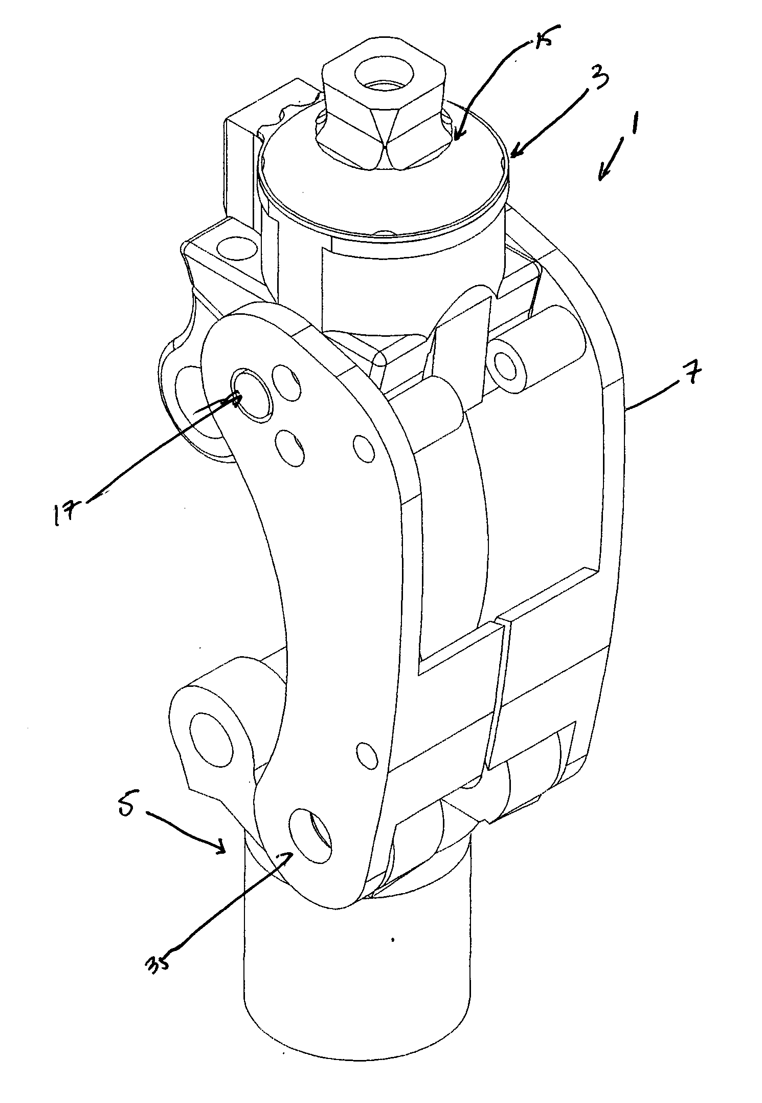
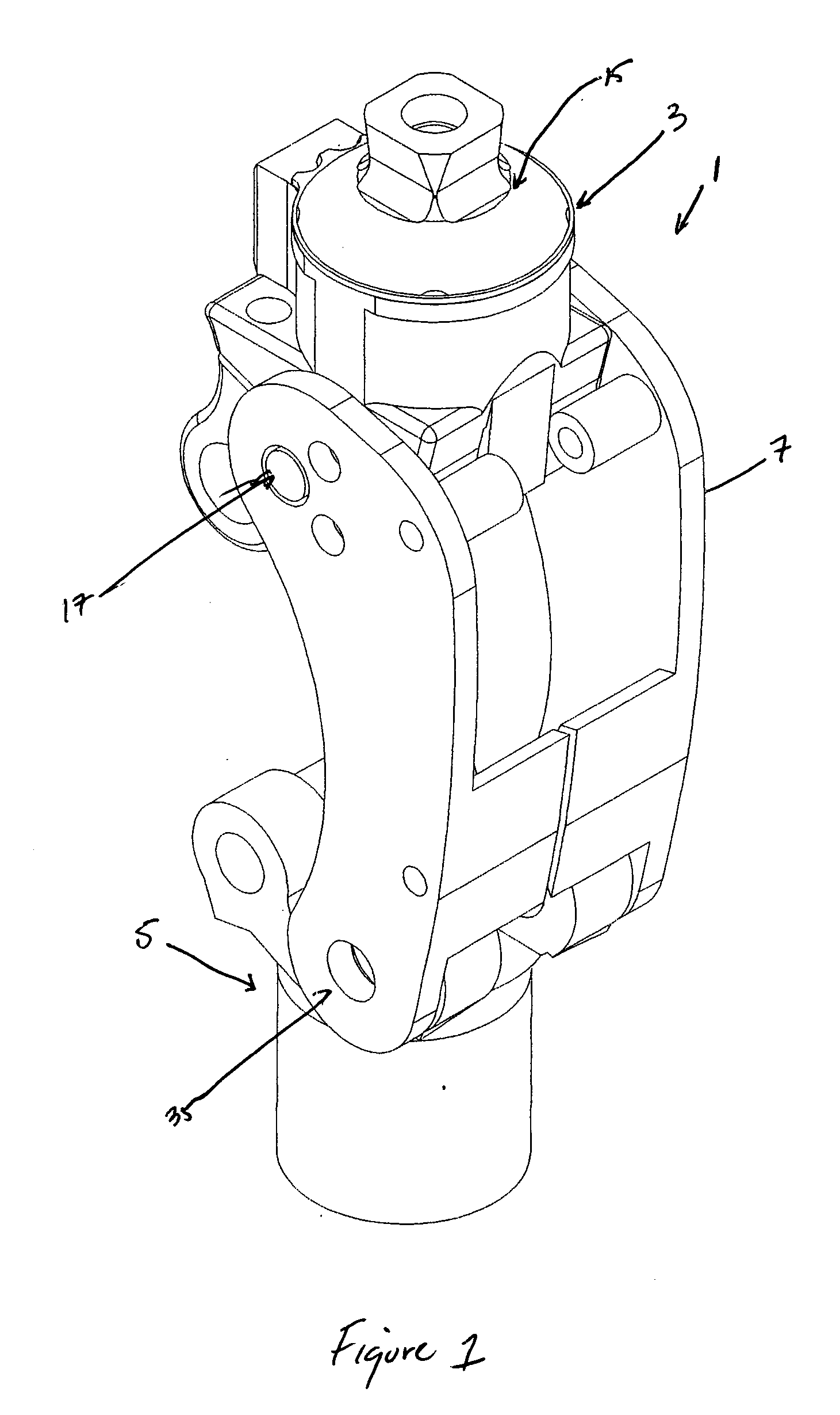
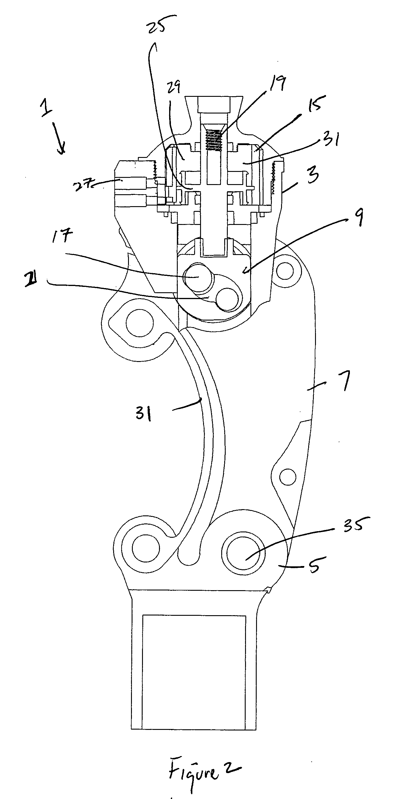
[0081] The present invention relates to a prosthetic knee that improves stability and flexion of a user during use. The mechanism has a braking mechanism to increase stance phase stability in a polycentric knee. Additionally, the knee uses a cam mechanism to control the flexion and extension of the knee. Moreover, the prosthetic knee uses a collapsible posterior linkage which allows the knee a small degree of flexion at heel strike while maintaining overall knee stability.

[0082] As illustrated in FIG. 1, the present invention generally relates to a prosthetic knee mechanism 1 having an upper portion 3 and a lower portion 5.

[0083] The upper portion 3 may connect to, and / or form part of the thigh component of a prosthesis. The lower portion 5 may connect to, and / or form part of the lower leg system of a prosthesis. A connection means and / or anterior linkage 7 may be positioned between the upper portion 3 and the lower portion 5. The anterior linkage 7 and / or connection means may con...


PUM


Abstract

A prosthetic knee mechanism that improves stability and flexion of an individual during use. The prosthetic knee mechanism has a braking mechanism to increase stance phase stability in a polycentric knee. The combination of the braking mechanism with a polycentric knee increase stance stability and reduces frictional forces on the prosthetic knee components. The prosthetic knee mechanism uses a cam mechanism to control the flexion and extension of the knee. The cam mechanism also controls the speed at which the foot and shank swing. The prosthetic knee uses a collapsible posterior linkage which allows the knee to go into a small degree of flexion at heel strike while maintaining overall knee stability.

Description

TECHNICAL FIELD [0001] The present invention generally relates to a prosthetic limb. More specifically, the present invention relates to a knee mechanism that addresses the stability, flexability and flexion of a user during use of the knee. Specifically, the prosthetic knee mechanism uses a posterior linkage, a cam mechanism, and a braking mechanism that allow the knee to bend and shorten when subject to loading by a user. BACKGROUND OF THE INVENTION [0002] It is, of course, generally known that prosthetic knee designers have faced very difficult challenges when designing a limb for a user that may have lost one. Historically, when an individual lost a limb, there was very little that an individual could do to replace that limb with any mechanism that would function in the same or similar capacity of the original limb. Many times, an individual would likely have to resort to a crude manipulation of a material such as a peg or wood structure to take the place of the missing limb. Ho...

Claims


Application Information

Patent Timeline
IPC IPC(8): A61F2/62A61F2/64A61F2/68
CPCA61F2/644A61F2/68A61F2002/747A61F2002/745A61F2002/6818A61F2/74
Inventor BASSETT, DAVID
Owner BASSETT DAVID
Why Eureka
Try Eureka