Optical transmission system and optical transmission method

a transmission system and optical transmission technology, applied in the field of optical transmission systems and optical transmission methods, can solve the problems of increasing signal loss, affecting affecting the quality of transmitted signals, so as to improve the phase stability of transmitted signals, simplify system configurations, and reduce signal loss

Active Publication Date: 2012-10-18
INTER UNIV RES INST NAT INST OF NATURAL SCI
View PDF1 Cites 14 Cited by
  • Summary
  • Abstract
  • Description
  • Claims
  • Application Information

AI Technical Summary

Benefits of technology

[0011]With the optical transmission system according to the present invention, it is possible to simplify a system configuration and therefore to reduce signal loss and in turn improve the phase stability of the transmitted signal with the result that digitization and larger packaging densities become easy to achieve and that an advantage is given to multipoint transmission compensation.

Problems solved by technology

On the contrary, the phase-locked loop circuit, the microwave signal phase shifter, or the like complicates a system configuration, thereby increasing signal loss, which in turn inhibits the improvement in the phase stability of a transmitted signal.
This further leads to a problem that digitization and larger packaging densities become hard to achieve and that a disadvantage is imposed on multipoint transmission compensation.

Method used


Image

  • Optical transmission system and optical transmission method
  • Optical transmission system and optical transmission method
  • Optical transmission system and optical transmission method

Examples


first embodiment

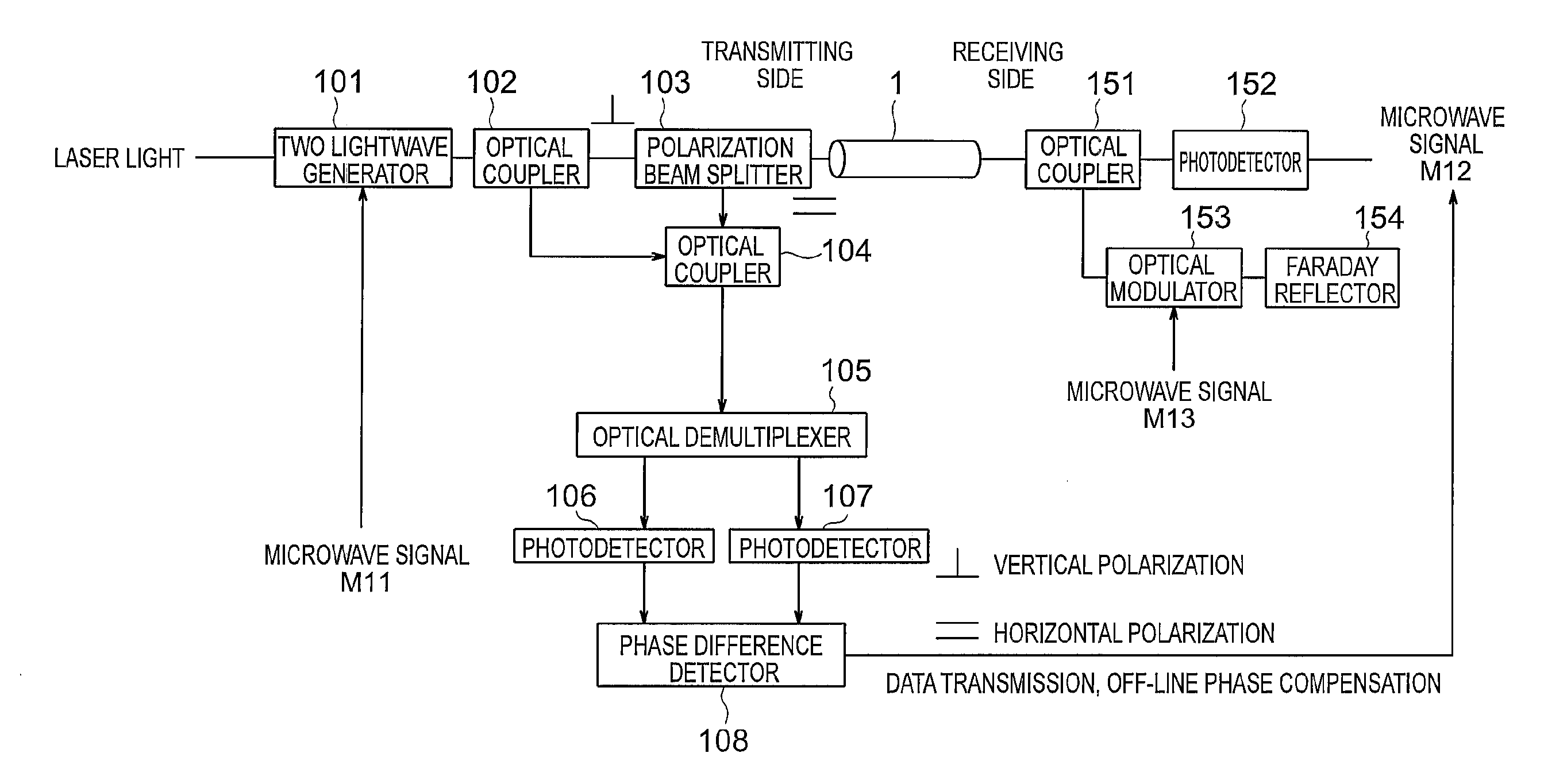
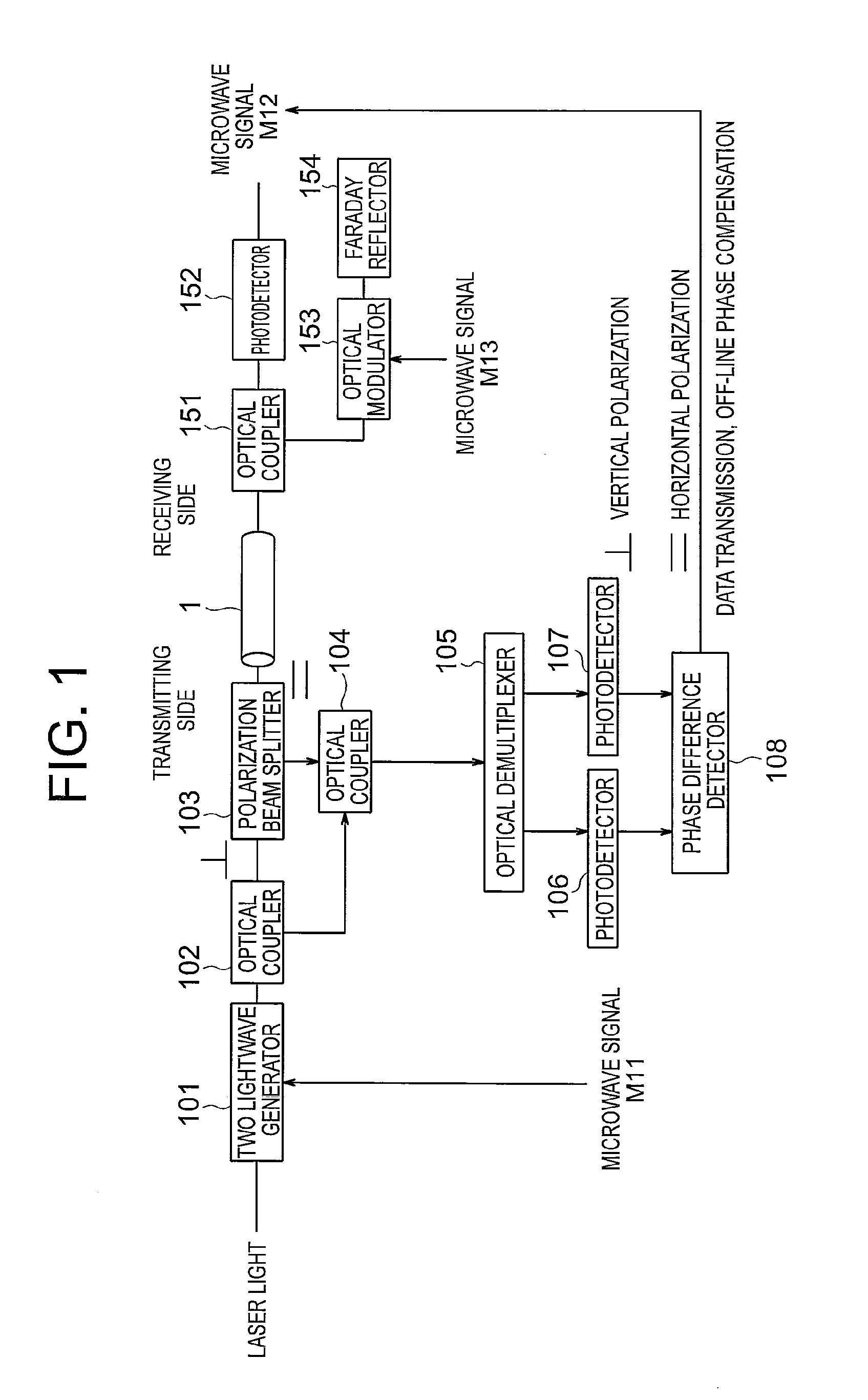
[0021]FIG. 1 is referenced to describe an optical transmission system according to a first embodiment of the present invention. FIG. 1 is a diagram illustrating a configuration of the optical transmission system according to the first embodiment of the present invention. Note that, hereinafter, the same reference symbols within the respective drawings indicate the same or equivalent components.

[0022]In FIG. 1, the optical transmission system according to the first embodiment of the present invention is provided on a transmitting side with: a two-lightwave generator 101 for generating two coherent optical signals (having wavelengths λ1 and λ2) having different wavelengths from each other from laser light that has been input by using a microwave signal M11; an optical coupler 102 for distributing the two optical signals; a polarization beam splitter 103 for passing vertical polarization light between the optical coupler 102 and an optical fiber 1 and passing horizontal polarization li...

second embodiment

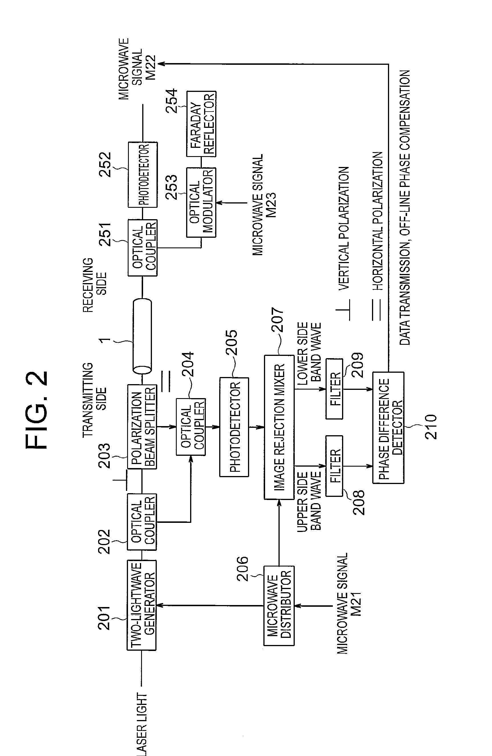
[0037]FIG. 2 is referenced to describe an optical transmission system according to a second embodiment of the present invention. FIG. 2 is a diagram illustrating a configuration of the optical transmission system according to the second embodiment of the present invention.

[0038]In FIG. 2, the optical transmission system according to the second embodiment of the present invention is provided on the transmitting side with: a two-lightwave generator 201 for generating two optical signals (having wavelengths λ3 and λ4) that differ from each other by a frequency of a microwave signal M21 described later; an optical coupler 202 for distributing the optical signals; a polarization beam splitter 203; an optical coupler 204 for mixing the optical signals; a photodetector 205 for converting the optical signals into microwave signals; a microwave distributor 206 for distributing the microwave signal M21; an image rejection mixer 207 for frequency-converting the microwave signals from the photo...

third embodiment

[0053]FIG. 3 is referenced to describe an optical transmission system according to a third embodiment of the present invention. FIG. 3 is a diagram illustrating a configuration of the optical transmission system according to the third embodiment of the present invention.

[0054]The optical transmission system according to the third embodiment of the present invention is a combination of the above-mentioned optical transmission systems according to the first and second embodiments, and FIG. 3 illustrates a configuration that supports a multichannel and a simultaneous operation of the high-frequency signal and the low-frequency signal.

[0055]In FIG. 3, the laser light (having a wavelength 1 (λ1 and λ2)) indicated on the upper stage and the laser light (having a wavelength 2 (λ3 and λ4)) indicated on the lower stage are different from each other in optical wavelength. In the configuration that supports the simultaneous operation for a high-frequency signal and for a low-frequency signal, ...


PUM


Abstract

An optical transmission system includes: a two-lightwave generator for generating optical signals having wavelengths λ1 and λ2 from laser light; a photodetector for detecting a microwave signal M12 from two optical signals distributed by an optical coupler; an optical modulator for frequency-shifting the two optical signals; a Faraday reflector for reflecting the two optical signals; an optical coupler for mixing the two optical signals that have been reflected by the Faraday reflector, frequency-shifted again, transmitted by an optical fiber, and guided by a polarization beam splitter, with two optical signals distributed by an optical coupler; an optical demultiplexer for wavelength-dividing four mixed optical signals into optical signals having the wavelengths λ1 and λ2; photodetectors for detecting respective beat signals of the wavelength-divided optical signals having λ1 and λ2; and a phase difference detector for detecting a phase difference between the beat signals of the optical signals having λ1 and λ2.

Description

BACKGROUND OF THE INVENTION[0001]1. Field of the Invention[0002]The present invention relates to an optical transmission system and an optical transmission method in which round-trip transmission phase compensation data is acquired at time intervals synchronized with integration timings at a signal transmission destination to perform transmission phase compensation in a postprocessing in a case where an integration processing is performed for a time shorter than several seconds at the signal transmission destination.[0003]2. Description of the Related Art[0004]FIG. 6 illustrates the effect of an improvement in a phase stability of a transmission signal using a transmission phase compensation device in the optical transmission systems disclosed in Japanese Patent Application Laid-open Nos. 2009-060241 and 2011-071700 in the form of a relationship between the measured phase stability and time (for example, 80 GHz and a transmission path length of 10 km).[0005]FIG. 6 uses an internatio...

Claims


Application Information

Patent Timeline
Patent Type & Authority Applications(United States)
IPC IPC(8): H04J14/06H04B10/071H04B10/2575H04B10/516H04B10/61
CPCH04B10/0799H04J14/02H04J14/06H04B10/2507
Inventor KIUCHI, HITOSHI
Owner INTER UNIV RES INST NAT INST OF NATURAL SCI
Why Eureka
Try Eureka