Receive system for high q antennas in nqr and a method of detecting substances

receiver technology, applied in the field of nuclear quadrupole resonance (nqr) spectroscopic devices, can solve the problems of significant dead-time between the application pulse and the commencement of the receive period, resistive losses within the circuit and to the environment, and several deficits of employing a high q antenna. achieve the effect of rapid removal of energy and improving the phase stability of the response signal

Inactive Publication Date: 2006-02-16
QRSCI
View PDF19 Cites 16 Cited by
  • Summary
  • Abstract
  • Description
  • Claims
  • Application Information

AI Technical Summary

Benefits of technology

[0071] Preferably, the method includes rapidly removing energy from the antenna at the start of the receiving period.
[0072] Preferably, the method includes improving the phase stability of the response signal during the receiving period.

Problems solved by technology

The problem is how to excite and receive this signal in optimal ways to obtain the maximum Signal-to-Noise-Ratio (SNR).
Resistive losses do occur within the circuit and to the environment around the antennae including the sample.
There are, however, several deficits with employing a high Q antenna.
Until this energy is removed the receiver system will tend to be saturated by the induced ringing voltages, causing a significant dead-time between the applied pulse and commencement of the receive period.
These devices can suffer from self-triggering given a high enough dv / dt or voltage amplitude.
(2) Small instrumental drifts or mistakes in tune frequency or Q can cause both amplitude and phase variations because of rapid changes in antenna reactance close to resonance.
As a consequence the phase stability of the receiver system is poorer in a high Q system.
This method limits the ultimate detection rate and false alarm rate.
In detection work, perhaps the biggest source of uncertainty comes from the temperature of the sample not being precisely known in the substance to be found.
Where a detection system employs high Q transmit and receive antennae tuned to a single frequency there will be a reduction in performance due to this offset.
It was recognized, however, that a system employing feedback resistance would introduce unacceptable thermal noise or high input capacitance from a large value resistor, whereas a system employing capacitive feedback would not.
The problem with this technique, however, is that it is difficult to match to a given antenna.
The technique does not give optimum receiver bandwidth or the best properties of a constant receiver phase across a temperature range of an NQR signal.
Furthermore, the use of capacitance in the feedback loop, which may not be convenient in a commercial amplifier, introduces the possibility of high frequency oscillation modes, which may obscure the NQR signal.

Method used


Image

  • Receive system for high q antennas in nqr and a method of detecting substances
  • Receive system for high q antennas in nqr and a method of detecting substances
  • Receive system for high q antennas in nqr and a method of detecting substances

Examples


first embodiment

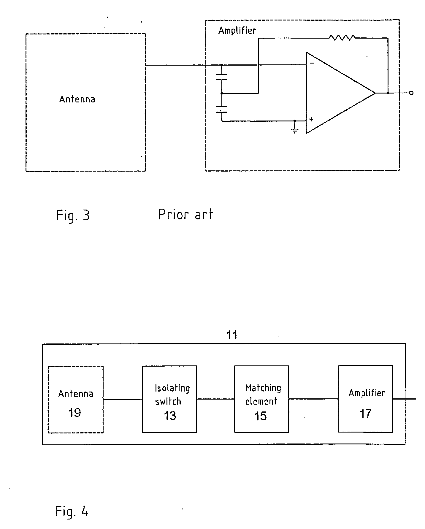
[0107] The best mode for carrying out the invention will now be described with respect to several embodiments. In accordance with the first embodiment, the isolating switch 13 comprises a low loss RF transformer controlled by a control circuit, the matching section 15 comprises a plurality of grounded gate JFETs (junction field effect transistors) connected in parallel, and the amplifier 17 comprises a high input impedance amplifier.

[0108] The arrangement of the isolating switch is as shown in FIG. 5, wherein a low loss RF transformer 21 with primary and secondary coils wound on a low-loss, high permeability material is provided. The primary side 21a of the transformer forms the series circuit to the signal receiving system 11 and the secondary side 21b is either opened or closed circuit to actuate a change in reactance and hence impedance, by virtue of a control circuit 23 and switch 25.

[0109] The isolating switch 13 does not conduct significant currents in its open state and is a...

second embodiment

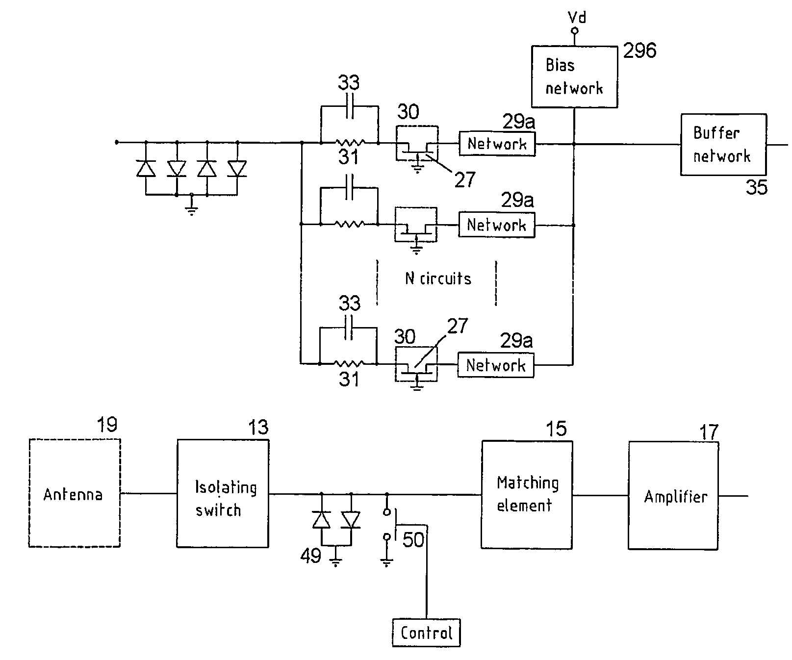
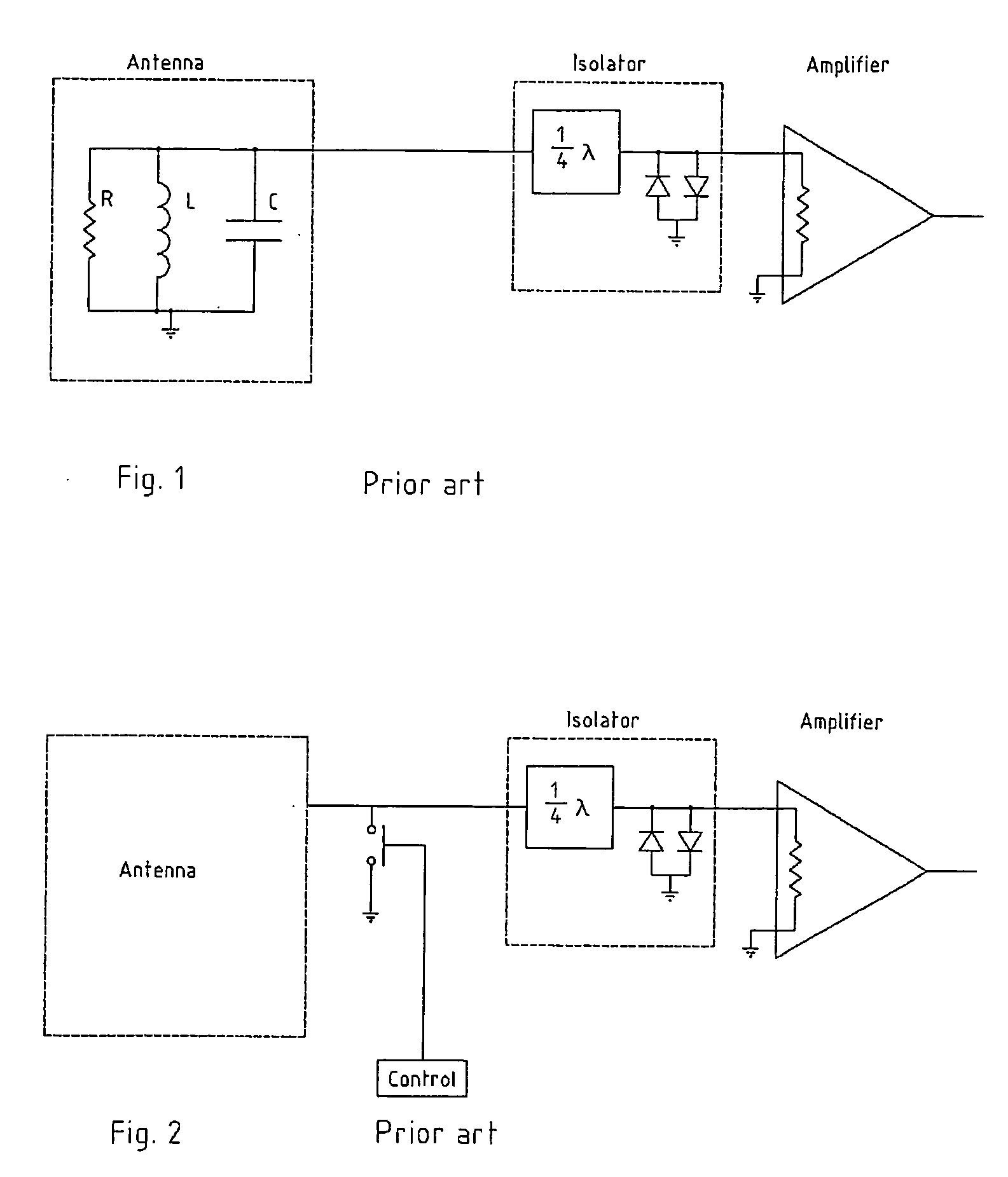
[0116] An example of the second embodiment is shown in FIG. 7, where the isolating switch 13 uses a quarter wave line 41 in place of the transformer 21, having an end 43 that is made a node or anti-node via opening or closing a conducting element 46. In this example, the ¼ wave line end 43 is terminated by back-to-back signal diodes 47, which automatically open and close depending on the level of the transmit signal sensed by the control 23.

[0117] The third embodiment is substantially identical to the first or second embodiments, except that the amplifier 17 is replaced by a feedback amplifier whose intention is to lower its input impedance without introducing noise from a resistive feedback circuit element, as shown in FIG. 8. The network box 60 could be a resistor, capacitor or a series of circuits which create a feedback amplifier.

[0118] The fourth embodiment is substantially identical to the first or second embodiments, except that in this embodiment the matched section 15 is c...


PUM


Abstract

A receiving system (11) for connection to an antenna arrangement (19) for detecting response signals from a substance having quadrupolar nuclei excited so as to produce nuclear quadrupole resonance in certain of the quadrupolar nuclei. A method for receiving a response signal via the antennae arrangement (19) is also described. The receiving system (11) includes an amplifier (17) to amplify the received response signal from the antenna arrangement (19) for subsequent processing, a matching section (15) to match the amplifier (17) to the antenna (19), and an isolating switch (13) to isolate the antenna from the receiving system (11). The matching section (15) noise matches the receiving system (11) to the antenna (19) during a receiving period to reduce the Q factor of the antenna without significantly degrading the signal to noise ratio. The isolating switch (13) isolates the receiving system (11) from the antenna (19) during a transmitting period when an excitation signal is transmitted by the antenna (19) to irradiate the substance. It also electrically connects the receiving system (11) to the antenna during the receiving period immediately after the transmitting period.

Description

FIELD OF THE INVENTION [0001] The present invention relates to Nuclear Quadrupole Resonance (NQR) spectroscopic devices and methods of detecting using such devices. More particularly the invention relates to those devices that require extended bandwidth, phase-stability or reduced Q factor during reception of a response signal sourced from a substance containing quadrupolar nuclei that are appropriately excited. These devices typically contain a high Q resonant circuit antenna that is designed to intercept magnetic field variations and convert them to output voltages to be amplified, so that the NQR response signal may be recorded. [0002] Throughout the specification, unless the context requires otherwise, the word “comprise” or variations such as “comprises” or “comprising”, will be understood to imply the inclusion of a stated integer or group of integers but not the exclusion of any other integer or group of integers. BACKGROUND ART [0003] The following discussion of the backgrou...

Claims


Application Information

Patent Timeline
Patent Type & Authority Applications(United States)
IPC IPC(8): G01V3/00G01R33/36G01R33/44
CPCG01R33/3621G01R33/441G01R33/3628
Inventor FLEXMAN, JOHN HAROLDHAYES, PETER ALARICCHISHOLM, WARICK PAULMIKHALTSEVITCH, VASSILE TIMOFEEVITCHRUDAKOV, TARAS NIKOLAEVITCH
Owner QRSCI
Why Eureka
Try Eureka