
Device and method for purifying exhaust gas from industrial vehicle engine

a technology for industrial vehicles and exhaust gas, applied in mechanical equipment, machines/engines, electric control, etc., can solve the problems of combusting of particulates accumulated in filters, long time, and long time an engine is used continuously, and achieves good fuel efficiency and effective reprocessing

Inactive Publication Date: 2005-07-21
TOYOTA IND CORP
View PDF7 Cites 26 Cited by
  • Summary
  • Abstract
  • Description
  • Claims
  • Application Information

AI Technical Summary

Benefits of technology

[0005] The object of the present invention is to provide a technology for effectively reprocessing a collecting section that has collected particulates at a good fuel efficiency.

Problems solved by technology

Consequently, the particulates accumulated in the filter are combusted.
In the first technology wherein the particulates are combusted at a relatively low temperature utilizing NO2 in the exhaust gas, since the amount of NO and NO2 contained in the exhaust gas is small, it takes a longer time to reprocess an exhaust emission purifying apparatus compared to the second technology wherein the temperature of the exhaust gas is raised up to or higher than 600° C. Further, in the case of a forklift, an engine is often used in a state of low load or the length of time an engine is continuously used is often short, therefore, in such a case, the requisite condition for combustion by NO2 can not easily be secured.
For this reason, the first technology cannot be effectively used as the regeneration technology for a filter in a forklift.
However, in this case, although compulsory reprocessing of the filter becomes possible, operation at high engine load and high engine speed is required, thereby lowering the fuel efficiency.

Method used


Image

  • Device and method for purifying exhaust gas from industrial vehicle engine
  • Device and method for purifying exhaust gas from industrial vehicle engine
  • Device and method for purifying exhaust gas from industrial vehicle engine

Examples


first embodiment

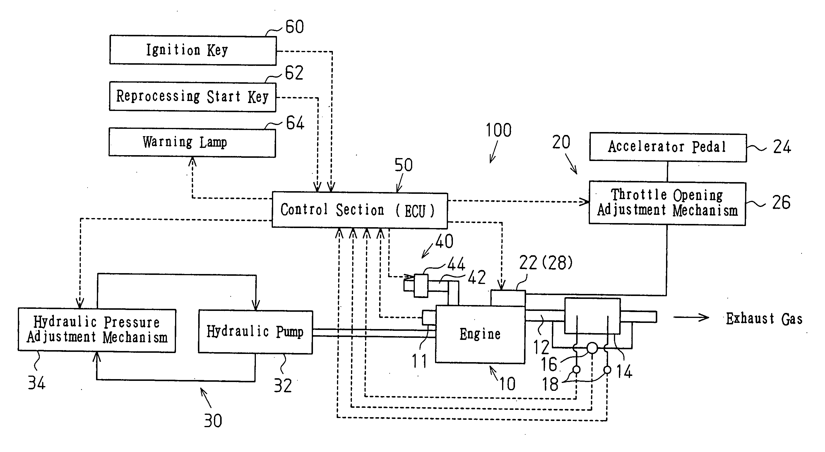
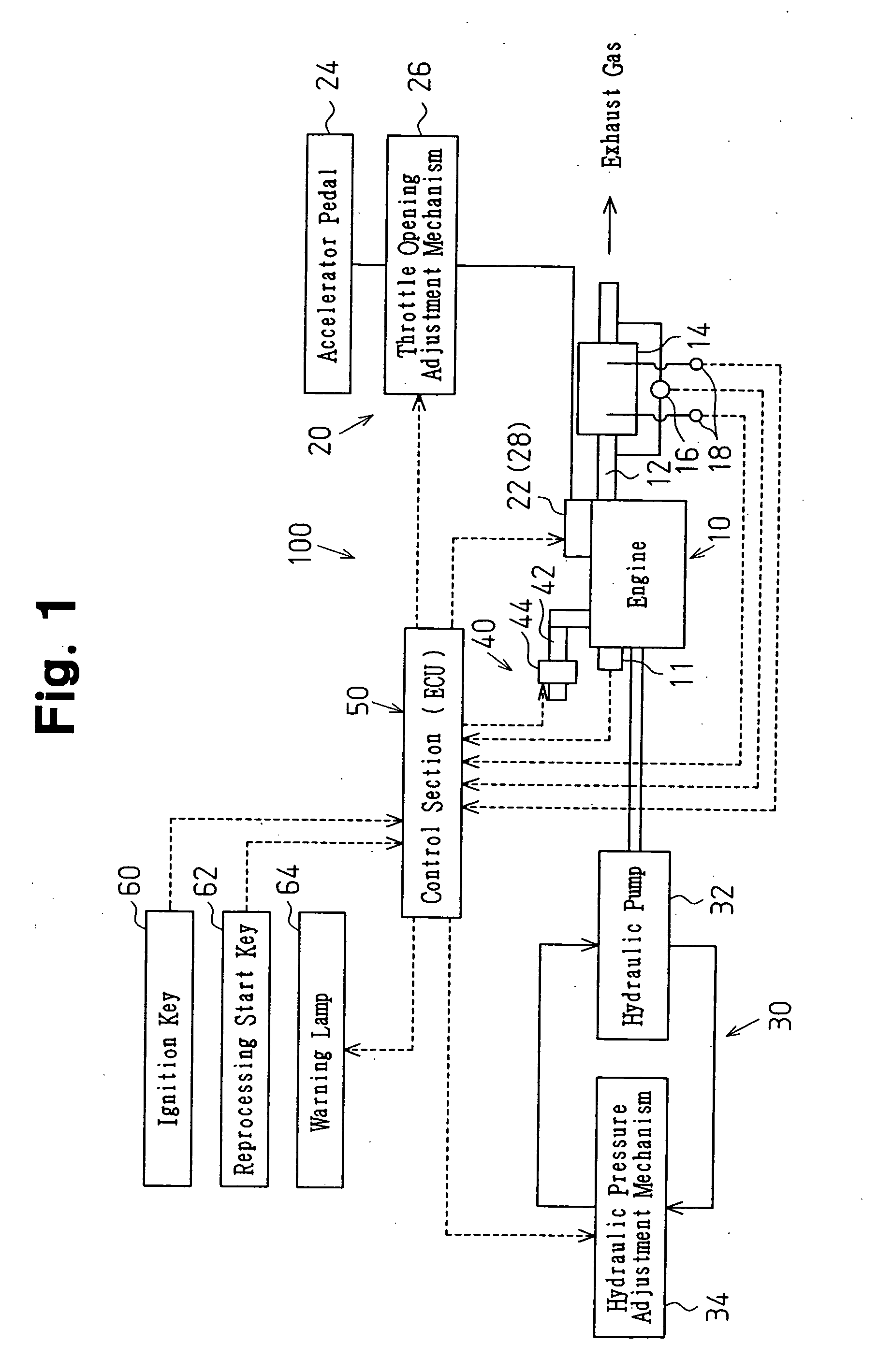
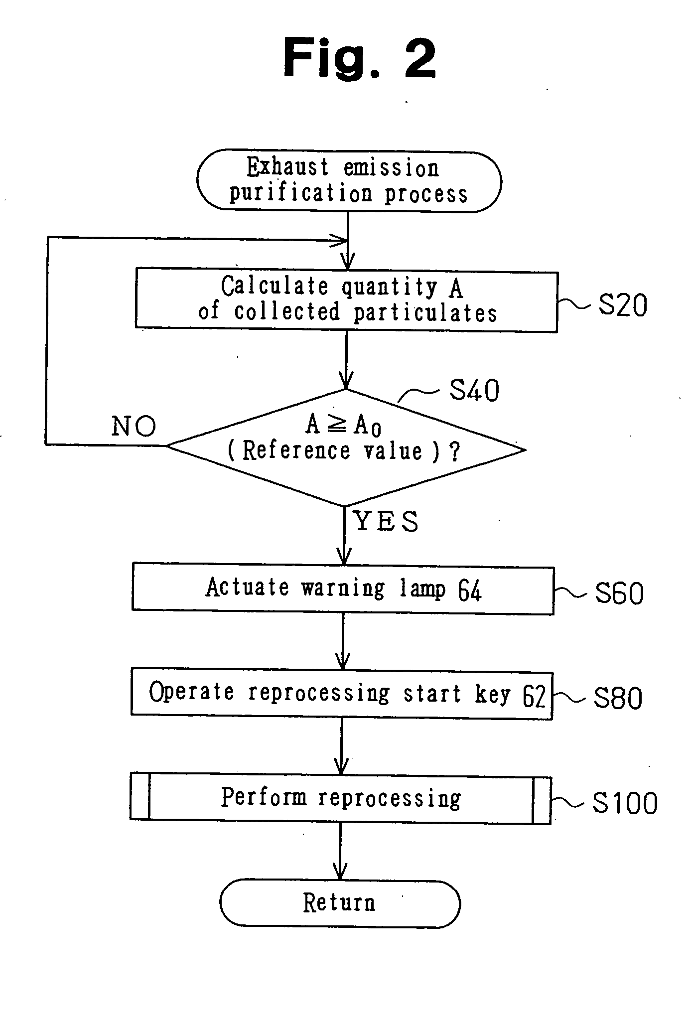
[0013] the present invention will be described below referring to FIGS. 1 to 3, and 5. It is to be noted that this embodiment is an explanation of an example of the present invention applied to the technology of a purifying process for the exhaust gas emitted from a diesel engine amounted on a forklift as an industrial vehicle.

[0014] As shown in FIG. 1, a diesel engine 10 as an engine for an industrial vehicle is equipped with an exhaust emission purifying apparatus 100. The exhaust emission purifying apparatus 100 performs a purifying process for the exhaust gas emitted from the diesel engine 10. The exhaust emission purifying apparatus 100 includes a collection section 14 disposed in an exhaust passage 12 in a section downstream of the diesel engine 10, an injection amount adjustment section 20, an engine load adjustment section 30, an air intake restriction adjustment section 40, and a control section 50. It is to be noted that the diesel engine 10 is equipped with an engine spee...

second embodiment

[0031] Next, the present invention is explained in accordance with the flowchart shown in FIG. 4, referring to FIGS. 1 to 3. In the reprocessing shown in FIG. 4, steps S110 to S113, the same steps shown in FIG. 3, are performed. When the result of step S112 is YES, that is, if the value of the throttle opening degree M is determined to be equal to or greater than the second reference value, the process proceeds to step S120.

[0032] In step S120, the control section 50 detects the differential pressure ΔP at the collection section and compares such detected value with a third reference value BkPa. If the result of step S120 is YES, that is, if such detected differential pressure ΔP is determined to be equal to or less than the third reference value, in other words, if the amount of accumulated particulates at the collection section 14 is less than the predetermined control value, the process proceeds to step S122.

[0033] In step S122, the control section 50 detects the outlet temperat...


PUM


Abstract

An exhaust emission purifying apparatus 100 performs the purification process of the exhaust gas emitted from a diesel engine 10 of a forklift. The exhaust emission purifying apparatus 100 elevates the temperature of the exhaust gas for the purpose of reprocessing a collection section 14 on the predetermined temperature condition using a fuel injection adjustment section 20, an engine load adjustment section 30, and an air intake restriction adjustment section 40. Thereby the temperature of the exhaust gas is set at the predetermined temperature, while keeping low the engine speed and the engine load. This construction makes it possible to improve the fuel consumption in reprocessing the collection section 14.

Description

TECHNICAL FIELD [0001] The present Invention relates to the technology for performing purifying processing of the exhaust gas emitted from an engine installed in an industrial vehicle, such as a forklift and the like. BACKGROUND ART [0002] Relatively many particulates (particulate matter) whose major component is carbon, for instance, are included in the exhaust gas emitted from a diesel engine of a forklift. The particulates are a cause of worsening of visibility and are subject to regulations as air pollutants, therefore, reduction of such particulates has been desired. In this regard, a technology is presented such that an exhaust emission purifying apparatus to collect and remove particulates is installed downstream of a diesel engine, and such exhaust emission purifying apparatus is suitably controlled in accordance with the state of operation. [0003] Conventionally, as the technology for reprocessing of an exhaust emission purifying apparatus, for example, the first and second...

Claims


Application Information

Patent Timeline
Patent Type & Authority Applications(United States)
IPC IPC(8): F01N3/023F01N9/00F01N11/00F02D41/02
CPCF01N3/023F01N3/0231F01N9/002F01N11/002F02D41/024Y02T10/47F02D41/1446F02D2200/0404F02D2200/0812Y02T10/26F02D41/029Y02T10/12Y02T10/40
Inventor NAKAMURA, MASAYA
Owner TOYOTA IND CORP
Learn More