Method and device for diagnosing gas sensor degradation

a technology of gas sensor and degradation, which is applied in the direction of specific gravity measurement, nuclear engineering, nuclear elements, etc., can solve the problems of hydrogen detector degraded, catalyst poisoned, detection accuracy drops,

Inactive Publication Date: 2005-07-21
SHIGA INT PATENT OFFICE +1
View PDF3 Cites 40 Cited by
  • Summary
  • Abstract
  • Description
  • Claims
  • Application Information

AI Technical Summary

Benefits of technology

[0058] According to the gas sensor degradation diagnosis device of the aforementioned constitution, while accurately grasping the state of a vehicle and, for example, the operatio

Problems solved by technology

Meanwhile, silicon in materials such as sealant used in a fuel cell can mix with the air off-gas, and when the hydrogen detector is exposed to this silicon during the catalytic reaction, the catalyst is poisoned.
As a result,

Method used


Image

  • Method and device for diagnosing gas sensor degradation
  • Method and device for diagnosing gas sensor degradation
  • Method and device for diagnosing gas sensor degradation

Examples


Embodiment Construction

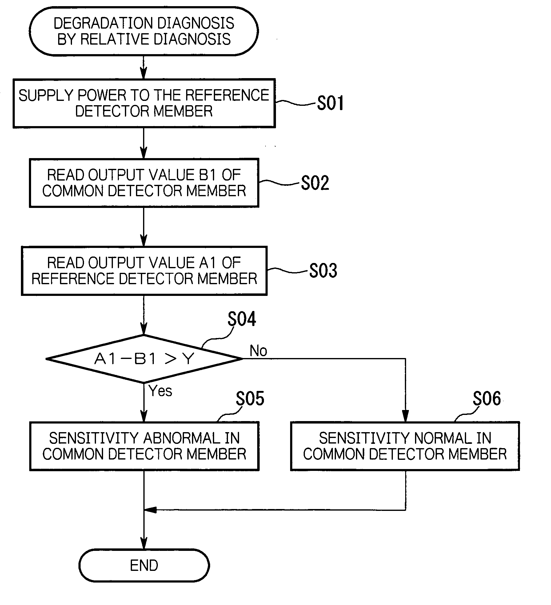
[0088] Below, the gas sensor degradation diagnosis device according to an embodiment of the present invention is explained referring to the drawings.

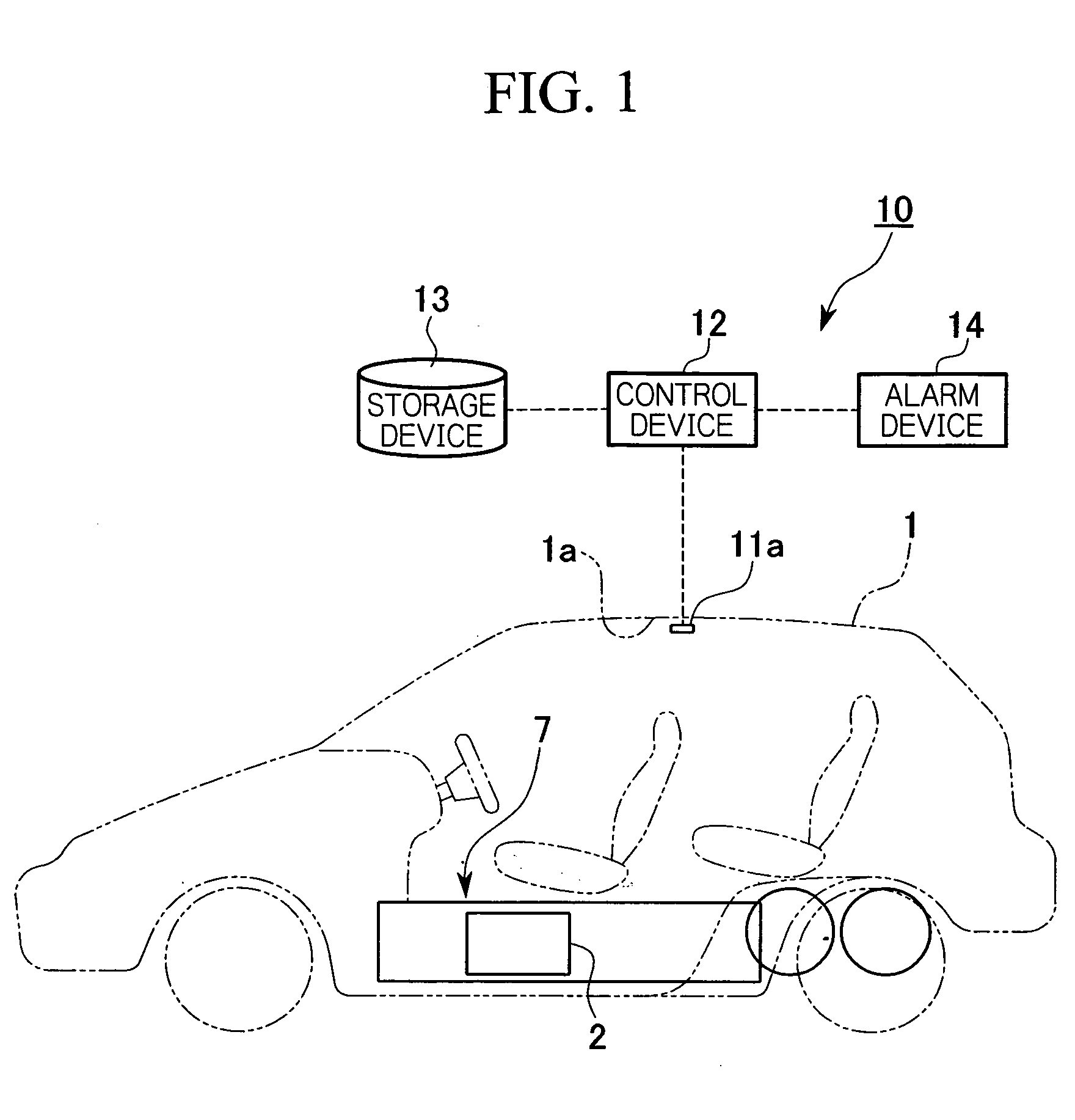
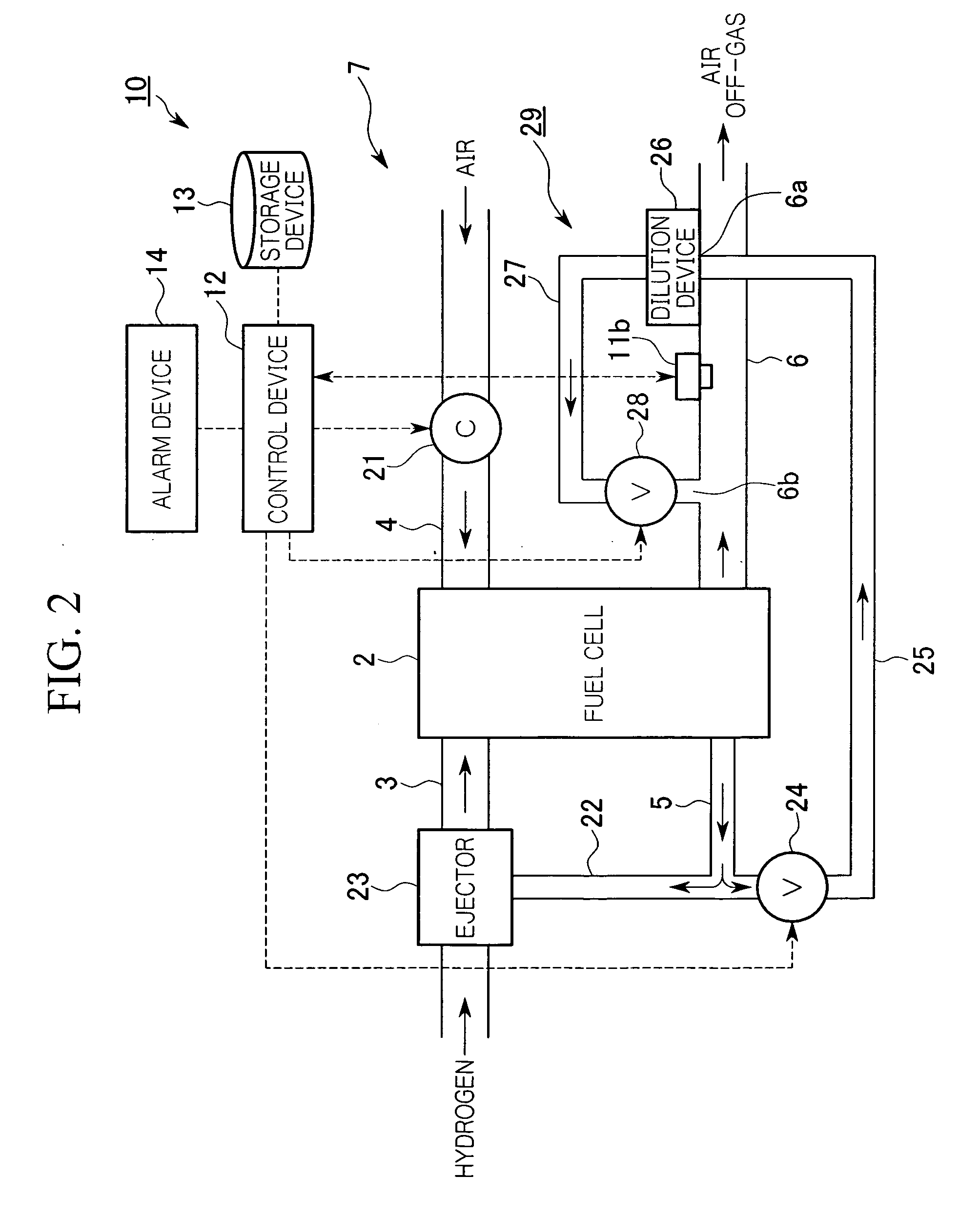
[0089] The gas sensor degradation diagnosis device according to the present embodiment includes a hydrogen sensor 11a for detecting hydrogen of the prescribed concentration, including zero, in the interior of a vehicle 1 such as a fuel cell vehicle as shown for example in FIG. 1 and devices such as control device 12, storage device 13 and alarm device 14 that diagnose whether or not each gas sensor is degraded with respect to the gas sensor such as hydrogen sensor 11b provided in the outlet side conduit 6 of the oxygen terminal side of the fuel cell system 7 including a fuel cell 2 and conduits 3, 4, 5, and 6 connected to the fuel cell 2, as shown for example in FIG. 2.

[0090] The control device 12 is connected to the hydrogen sensor 11a installed in the roof 1a of the vehicle and to hydrogen sensor 11b installed in the outlet side con...


PUM


Abstract

A degradation diagnosis method for simply performing degradation diagnosis of a gas sensor such as a hydrogen sensor. The hydrogen sensor has a reference detector member and common detector member, with each detector member respectively constituted of a detector element and temperature compensating element that form a pair. Power is normally supplied to the common detector member, which performs concentration detection of the hydrogen gas. When performing degradation diagnosis of this common detector member, concentration detection is performed simultaneously by each detector member for the gas of the prescribed hydrogen concentration by supplying power to both the common detector member and reference detector member and comparing the output value of the common detector member and the output value of the reference detector member.

Description

TECHNICAL FIELD [0001] This invention relates to a method and device for diagnosing degradation in gas sensors such as hydrogen sensors. BACKGROUND ART [0002] A solid polymer membrane fuel cell, for instance, has a stack comprised by stacking a plurality of cells formed by sandwiching a solid polymer electrolyte membrane from both sides by an anode and a cathode, with hydrogen fed to the anode as fuel, and air fed to the cathode as an oxidant. Hydrogen ions generated at the anode by a catalytic reaction move through the solid polymer electrolyte membrane to the cathode, where they cause an electrochemical reaction with oxygen to generate electricity. [0003] In fuel cells such as this kind of solid polymer membrane fuel cell, unreacted air discharged from the cathode (referred to as air off-gas) is normally discharged out of the system, in which case the hydrogen gas concentration in the air off-gas must be confirmed. [0004] Systems have been developed in the past for confirming the ...

Claims


Application Information

Patent Timeline
IPC IPC(8): G01N27/26G01N27/04G01N27/16G01N33/00H01M8/04H01M8/06
CPCG01N27/16G01N33/0031G01N33/005G01N33/007Y02E60/50H01M8/04097H01M8/0662H01M2250/20Y02T90/32H01M8/04089Y02T90/40
Inventor SASAKI, TAKASHIABE, HIROYUKIEGUCHI, TSUYOSHIKOJIMA, YASUSHISAITO, TAKASHISUZUKI, AKIHIRO
Owner SHIGA INT PATENT OFFICE
Why Eureka
Try Eureka