Gas-measuring device with an electrochemical sensor

a gas-measuring device and electrochemical technology, applied in special-purpose recording/indication devices, instruments, chemical methods analysis, etc., can solve the problems of not having an unlimited service life of electrochemical gas sensors, inability to guarantee continuous measurement function, and high cos

Active Publication Date: 2005-07-21
DRAGER SAFETY
View PDF8 Cites 6 Cited by
  • Summary
  • Abstract
  • Description
  • Claims
  • Application Information

AI Technical Summary

Benefits of technology

[0009] The advantage of the present invention is essentially that a status display, which displays the degree of depletion of the sensor to the user, is generated at the gas-measuring device on the basis of sensor-specific measured variables. The user thus obtains information on the optimal point in time for the replacement of the sensor. The measuring function of the gas sensor can thus be utilized over the longest period of time possible. The status display described in the present invention is not limited to electrochemical sensors, but it can also be used in case of catalytic or optical gas sensors or electrochemical systems such as batteries.
[0010] A trend curve is advantageously determined as a function of time in the evaluating circuit as a function of sensor-specific measured variables and compared with a predetermined limit value. The status display is activated when the function value of the trend curve has reached a predetermined limit value. It is useful in this connection to set a plurality of limit values, which are associated with individual status displays. The course of the trend curve can thus be followed better.
[0011] The sensor current is suitable for use as the sensor-specific measured variable in an amperometric fuel cell, the trend curve being formed by integration of the sensor current over time. The value of the integral of a brand new sensor, hereinafter called the current integral, is zero. The depletion of the sensor is also zero here, i.e., the sensor is suitable for use without restrictions. The closer the current integral comes to a predetermined limit value in the course of the use of the sensor, the greater will be the depletion of the sensor up to the complete consumption of the electrolyte or the anode material.
[0012] The reduction of the sensor sensitivity E, which assumes the maximum in the original state and steadily declines during the use of the device, is suitable for use as an alternative trend curve. The sensor sensitivity can be determined, for example, during the calibration cycles to be carried out routinely, and a compensating straight line is drawn through the individual measured values. The decline in the sensor sensitivity E from the maximum to a predetermined lower limit value is an indicator of the depletion of the sensor or of the complete depletion of the sensor.
[0013] A temperature sensor measuring the ambient temperature is expediently provided, and positive deviations and negative deviations from a mean temperature TM are provided as additional measured variables. Integrals of the positive temperature deviations and negative temperature deviations are then formed. The temperature sensor may be arranged either at the gas-measuring device itself or at the sensor.
[0014] Exemplary embodiments are shown in the drawings and will be explained in greater detail below. The various features of novelty which characterize the invention are pointed out with particularity in the claims annexed to and forming a part of this disclosure. For a better understanding of the invention, its operating advantages and specific objects attained by its uses, reference is made to the accompanying drawings and descriptive matter in which the preferred embodiments of the invention are illustrated.

Problems solved by technology

Electrochemical sensors, especially electrochemical gas sensors, usually do not have an unlimited service life.
The drawback of doing so is that needlessly high costs are incurred.
The drawback here is that the measuring function is not guaranteed continuously, because replacement of the sensor cannot always be carried out in a short time.
However, the prior-art process provides no information on how long the sensor can still be used for measurement purposes.

Method used


Image

  • Gas-measuring device with an electrochemical sensor
  • Gas-measuring device with an electrochemical sensor
  • Gas-measuring device with an electrochemical sensor

Examples


Embodiment Construction

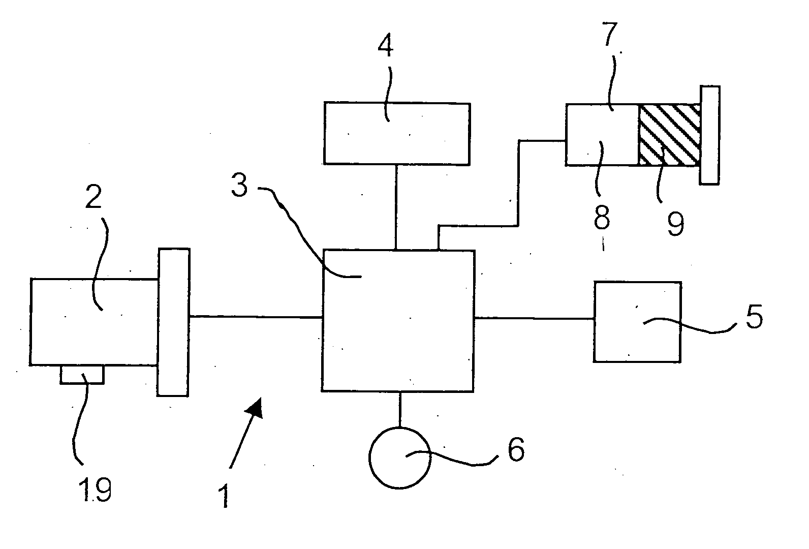
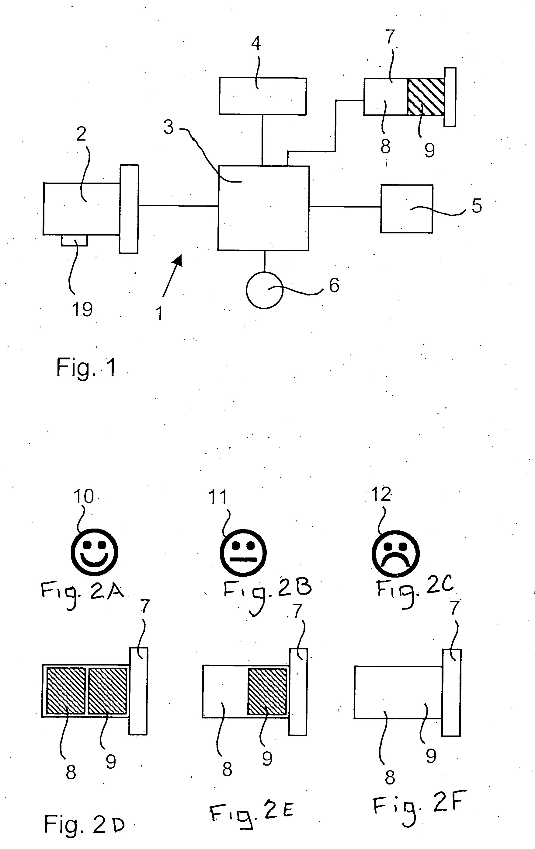
[0028]FIG. 1 schematically illustrates a gas-measuring device 1 with an amperometric fuel cell as the sensor 2, an evaluating circuit 3 for processing sensor-specific measured variables, a display unit 4 for measured values of a power supply unit 5, a temperature sensor 6 and with a status display 7 for the sensor depletion. The status display 7 has two display fields 8, 9, which are black or neutral depending on the state of the sensor. Only the display field 9 is blackened in the sensor state shown in FIG. 1, which approximately corresponds to a sensor 2 having been consumed by more than half and still has a high readiness for use with low failure probability.

[0029]FIGS. 2A-2E show different information states of the status display 7. FIG. 2D (the left-hand view) shows two blackened display fields 8, 9 that represent an unconsumed sensor 2 with a very high readiness for use and very low failure probability. In contrast, FIG. 2F (the right-hand view of the status display 7) shows ...


PUM

PropertyMeasurementUnit
temperatureaaaaaaaaaa
temperature Tmaaaaaaaaaa
concentrationaaaaaaaaaa

Abstract

A gas-measuring device has an electrochemical sensor and features such that the readiness for use is guaranteed for a determined period of time. A status display (7), is activated by the evaluating circuit (3) of the gas-measuring device. The status display (7) displays the degree of depletion of the sensor.

Description

CROSS REFERENCE TO RELATED APPLICATIONS [0001] This application claims the benefit of priority under 35 U.S.C. § 119 of DE 10 2004 002 289.5 filed Jan. 16, 2004, the entire contents of which are incorporated herein by reference.FIELD OF THE INVENTION [0002] The present invention pertains to a gas-measuring device with an electrochemical sensor. BACKGROUND OF THE INVENTION [0003] Electrochemical sensors, especially electrochemical gas sensors, usually do not have an unlimited service life. A point in time at which the technical properties are no longer sufficient for accomplishing the measuring task is reached at a certain time. In electrochemical gas sensors, one of these properties may be, for example, the level of the output signal at a certain gas concentration. Such sensors should therefore be exchanged and replaced with new ones at certain intervals. [0004] Both a safety engineering aspect and an economic aspect play a role concerning the point in time at which the replacement ...

Claims


Application Information

Patent Timeline
Patent Type & Authority Applications(United States)
IPC IPC(8): G01D3/00G01D21/00G01N21/01G01N27/00G01N27/16G01N27/26G01N27/416G01N27/49G01N33/00G01N37/00
CPCG01N27/4163G01N21/01G01N27/16G01N27/416G01N33/0065
Inventor STUDER, MATTHIASKESSEL, ROBERTNAUBER, ANDREASLEAHY, KATHLEENSAGASSER, GEROHUTH, ANDREAS
Owner DRAGER SAFETY
Why Eureka
Try Eureka