Method and apparatus for control of mobility-based ion species identification

a technology of mobility and ion species, applied in the field of methods and apparatus for detecting and identifying substances, can solve the problems of complex support system, large mass spectrometer, high cost, etc., and achieve the effect of improving system performan

Inactive Publication Date: 2005-07-21
DH TECH DEVMENT PTE
View PDF98 Cites 35 Cited by
  • Summary
  • Abstract
  • Description
  • Claims
  • Application Information

AI Technical Summary

Benefits of technology

[0018] A system of the invention, whether as method or apparatus, provides for control of ion species behavior in a time-varying filter field of an ion mobility-based spectrometer

Problems solved by technology

Furthermore, recent events have seen members of the general public exposed to dangerous chemicals in situations where previously no thought was given to such exposure.
However, mass spectrometers are quite expensive and large and are relatively difficult to deploy in the field.
Mass spectrometers also suffer from other shortcomings such as the need to operate at low pressures, resulting in complex support systems.
However, accurate i

Method used


Image

  • Method and apparatus for control of mobility-based ion species identification
  • Method and apparatus for control of mobility-based ion species identification
  • Method and apparatus for control of mobility-based ion species identification

Examples


Embodiment Construction

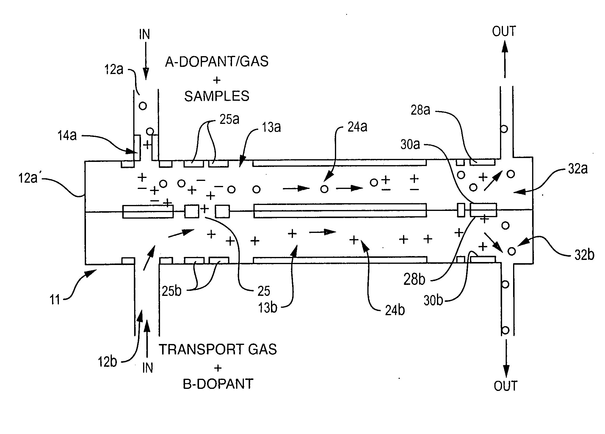
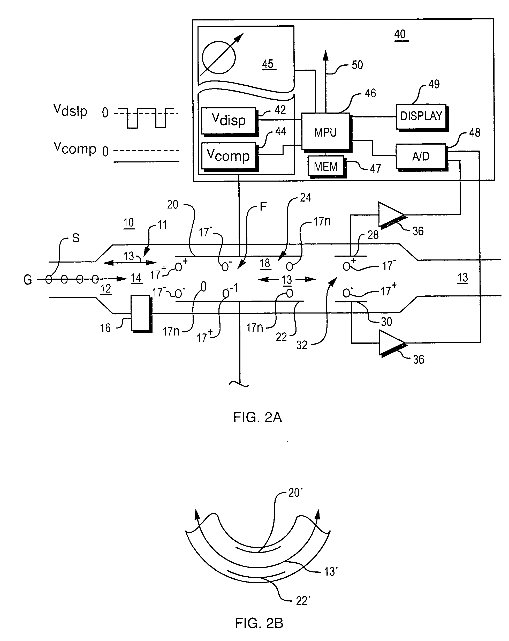
[0090] Illustrative DMS embodiments of the present invention are shown in FIG. 2A, 2B, and 2C. In the embodiment of FIG. 2A, apparatus 10 has an inlet 12 that accommodates the flow of a carrier gas G carrying sample S into the device and then along flow channel 13. The sample is drawn from the environment or received from a front end device, such as a gas chromatograph, and flows from inlet 12 to ionization region 14 along the flow path.

[0091] Compounds in the sample are ionized by an ionization source 16 as the sample flows through ionization region 14, creating a set of ionized molecules 17+, 17−, accompanied by some neutral molecules 17n of various chemical species. Ionized monomers and / or dimers are created during such ionization. Also clusters of ions may be created when a monomer combines with water molecules or other background molecules, in an ionized combination.

[0092] The ions are carried by a gas stream (sometimes referred to as a carrier gas) through stages of the syst...


PUM


Abstract

System for control of ion species behavior in a time-varying filter field of an ion mobility-based spectrometer to improve species identification, based on control of electrical and environmental aspects of sample analysis.

Description

RELATED APPLICATIONS [0001] This patent application is a continuation of U.S. patent application Ser. No. 10 / 462,206 which is a continuation-in-part of U.S. patent application Ser. No. 10 / 321,822 filed Dec. 16, 2002, a continuation-in-part of U.S. patent application Ser. No. 10 / 123,030 filed Apr. 12, 2002, and a continuation-in-part of U.S. patent application Ser. No. 10 / 187,464 filed Jun. 28, 2002, and claims the benefit of U.S. Provisional Application No. 60 / 389,400 filed Jun. 15, 2002, claims the benefit of U.S. Provisional Application No. 60 / 398,616 filed Jul. 25, 2002, claims the benefit of U.S. Provisional Application No. 60 / 418,671 filed Oct. 15, 2002, claims the benefit of U.S. Provisional Application No. 60 / 453,287 filed Mar. 10, 2003, and claims the benefit of U.S. Provisional Application No. 60 / 468,306 filed May 6, 2003. The entire teachings of the above-identified applications are incorporated herein by reference.FIELD OF THE INVENTION [0002] This invention relates to me...

Claims


Application Information

Patent Timeline
IPC IPC(8): G01N27/64G01N33/22H01J49/40
CPCG01N27/624H01J49/0031G01N33/22
Inventor MILLER, RAANAN A.NAZAROV, ERKINJON G.KRYLOV, EVGENYEICEMAN, GARY A.
Owner DH TECH DEVMENT PTE
Why Eureka
Try Eureka