PMBDCM and two phase SRM motor, two phase SRM rotor and stator, and coil wrap for PMBDCM and SRM motors

a two-phase srm motor and srm rotor technology, applied in the direction of synchronous motors, magnetic circuit shapes/forms/construction, windings, etc., can solve the problems of low torque density, nonlinear relationship, and inability of tpsrm b>100/b> to self-start in both directions of rotation, so as to reduce vibration, improve tpsrm reliability, and reduce acoustic noise

Inactive Publication Date: 2005-07-21
VIRGINIA TECH INTPROP INC +1
View PDF22 Cites 31 Cited by
  • Summary
  • Abstract
  • Description
  • Claims
  • Application Information

AI Technical Summary

Benefits of technology

[0041] A further object of the invention is to reduce the acoustic noise produced by the TPSRM, by placing its stator poles in corners of the stator laminations.
[0042] A further object of the invention is to reduce vibration and improve reliability of the TPSRM by tying stator windings of the TPSRM to the stator iron, with a tie-wrap that is inserted from the base of the windings, tightened, and welded to secure the windings against acceleration.
[0043] A further object of the invention is to place windings of the TPSRM flat against a smooth-faced inner periphery of the TPSRM's stator back iron, thus enabling a tight binding of the coil to resist vibrations, induced by the normal forces, and reduce acoustic noise.

Problems solved by technology

Therefore, exciting one or both phase windings does not help in moving the rotor from its stand-still position.
Therefore, TPSRM 100 is inherently incapable of self-starting in both directions of rotation, if provision is not made to eliminate these simultaneous zero-torque instances.
The disadvantage of such an approach is that wider rotor poles are employed, giving way to low torque density and a nonlinear relationship between the flux and rotor position.
Due to the nonlinear relationship between the flux and rotor position, the TPSRM has a large torque ripple and a varying torque constant, thus making control of the machine difficult.
A control system to achieve the simultaneous excitation is presented, though this control system does not provide current profiling due to its perceived complexity.
Moreover, these stepped air gap approaches do not significantly alter the requirements of a regular two-phase SRM.
The disadvantage of this approach is that one set of rotor poles has to be twice or more as wide as the other set of rotor poles, resulting in high rotor iron volume and weight.
Thus, these approaches reduce the power density of the machine.
Furthermore, these approaches complicate the control system, due to the many different modes that exist in the fluxing of the machine phases.
Some of the above described related art approaches to providing a self-starting TPSRM have an unevenness in the mechanical structure of the rotor, resulting in a non-uniform air gap when the stator and rotor poles align.
These approaches are prone to normally-induced forces and, hence, may have a slightly higher acoustic noise.

Method used


Image

  • PMBDCM and two phase SRM motor, two phase SRM rotor and stator, and coil wrap for PMBDCM and SRM motors
  • PMBDCM and two phase SRM motor, two phase SRM rotor and stator, and coil wrap for PMBDCM and SRM motors
  • PMBDCM and two phase SRM motor, two phase SRM rotor and stator, and coil wrap for PMBDCM and SRM motors

Examples


Embodiment Construction

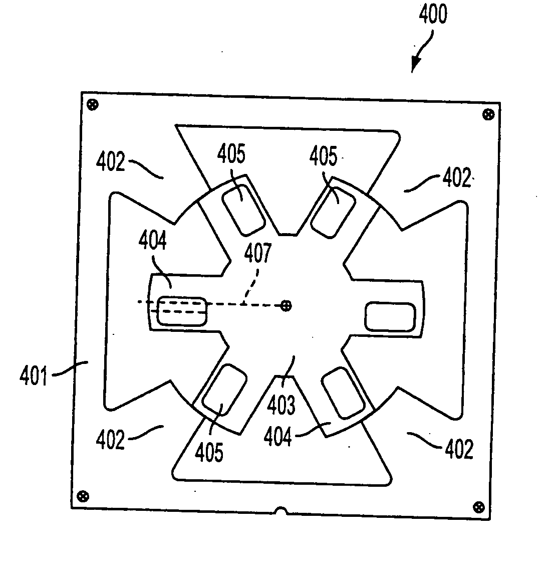
[0089] A first embodiment of the invention is drawn toward providing an electromagnetic torque for all rotor positions of a two-phase switched reluctance machine (TPSRM), without affecting the uniform air gap between the stator and rotor poles during their alignment and without increasing the rotor pole arc. Instead, an equivalent phase displacement of flux linkages can be achieved by providing a slot (i.e., hole) in the rotor poles. The slot can have a variety of shapes.

[0090]FIG. 4 illustrates a TPSRM having off-center slots in its rotor poles. A TPSRM 400 has a stator 401 with four salient stator poles 402 and a rotor 403 with six salient rotor poles 404. Each rotor pole 404 has a rotor pole slot 405 that is offset from a central radial axis 407 of the respective rotor pole 404 to provide a preferred path for the flux to flow between stator 401 and rotor 403. Making the rotor pole slot axis uneven toward one side reduces the flow of flux on that side by increasing the air gap re...


PUM


Abstract

A two-phase switched reluctance motor in an embodiment includes a plurality of salient rotor poles that each have asymmetric reluctances about a central radial axis of the respective rotor pole. Each of the rotor poles has the same width, and the rotor poles are operable to provide preferential torque generation in one direction of rotation for all rotor positions. Such preferential torque generation occurs under the influence of an electromagnetic flux, which is provided by a plurality of salient stator poles having substantially the same width as the rotor poles.

Description

CROSS-REFERENCE TO RELATED APPLICATIONS [0001] This application claims priority to U.S. Provisional Application Nos. 60 / 382,608, 60 / 382,609, and 60 / 382,610 filed May 24, 2002. Additionally, the application hereby incorporates by reference the disclosures provided in Applicant's co-pending PCT International Applications, having Attorney Docket Nos. L1081.03101, L1081.03102, L1081.03104, and L1081.03105 filed on the same date herewith.BACKGROUND OF THE INVENTION [0002] 1. Field of the Invention [0003] The invention relates to multiple-phase switched reluctance machines (SRMs) and, more specifically, to two-phase self-starting. SRMs. Additionally, the invention relates to SRMs and permanent magnet brushless direct current (dc) machines (PMBDCMs) and, more specifically, to reducing vibration and acoustical noise in SRMs and PMBDCMs. [0004] 2. Description of Related Art [0005] Related art two-phase switched reluctance machines (TPSRMs) do not produce electromagnetic torque at certain rot...

Claims


Application Information

Patent Timeline
Patent Type & Authority Applications(United States)
IPC IPC(8): H02K17/00H02K19/10H02K19/24
CPCH02K19/103H02K1/246
Inventor RAMU, KRISHNANSTALEY, AMANDA MARTIN
Owner VIRGINIA TECH INTPROP INC
Why Eureka
Try Eureka