Acoustic wave touch detecting apparatus

a touch detection and detecting device technology, applied in static indicating devices, instruments, specific gravity measurements, etc., can solve the problems of causing the controller to throw off the proper judgment, the controller's vibration and generation of voltage, and the increase of manufacturing steps, so as to reduce manufacturing costs, effective scattering and eliminating spurious waves

Active Publication Date: 2005-07-21
ELO TOUCH SOLUTIONS INC
View PDF20 Cites 18 Cited by
  • Summary
  • Abstract
  • Description
  • Claims
  • Application Information

AI Technical Summary

Benefits of technology

[0009] The present invention has been developed in view of the above points. It is an object of the present invention to provide an acoustic wave contact detecting apparatus, which is capable of effectively scattering and eliminating spurious waves, with increased productivity and reduced manufacturing costs.
[0025] The acoustic wave generating means and the spurious wave scattering means may be formed by printing. In this case, the productivity is increased and the manufacturing costs are reduced, because efficient production is enabled by automated printing, in addition to enabling effective scattering of spurious waves. The acoustic wave generating means and the spurious wave scattering means may alternatively be formed by etching. In this case also, productivity is increased and the manufacturing costs are reduced, because a single method can be used for forming both means, in addition to enabling effective scattering of spurious waves.

Problems solved by technology

If these spurious waves are reflected along the substrate and reach the sensor side converters, they cause these converters to vibrate and generate voltages.
These voltages are received as noise, and throw off proper judgment by the controller.
The adhesive attachment operation is manually performed, therefore increasing the manufacturing steps and reducing productivity.
As a result, there is a problem that manufacturing costs are increased.

Method used


Image

  • Acoustic wave touch detecting apparatus
  • Acoustic wave touch detecting apparatus
  • Acoustic wave touch detecting apparatus

Examples


Embodiment Construction

[0041] Preferred embodiments of the acoustic wave contact detecting apparatus (hereinafter, simply referred to as “apparatus”) will be described with reference to the attached drawings.

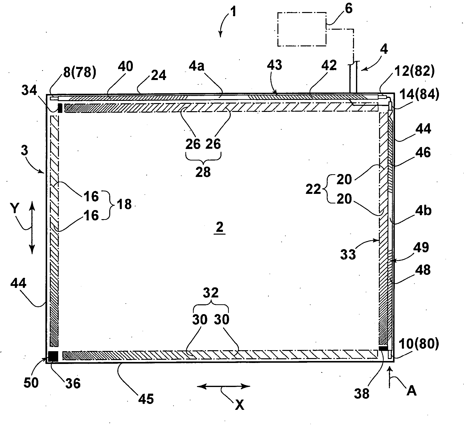
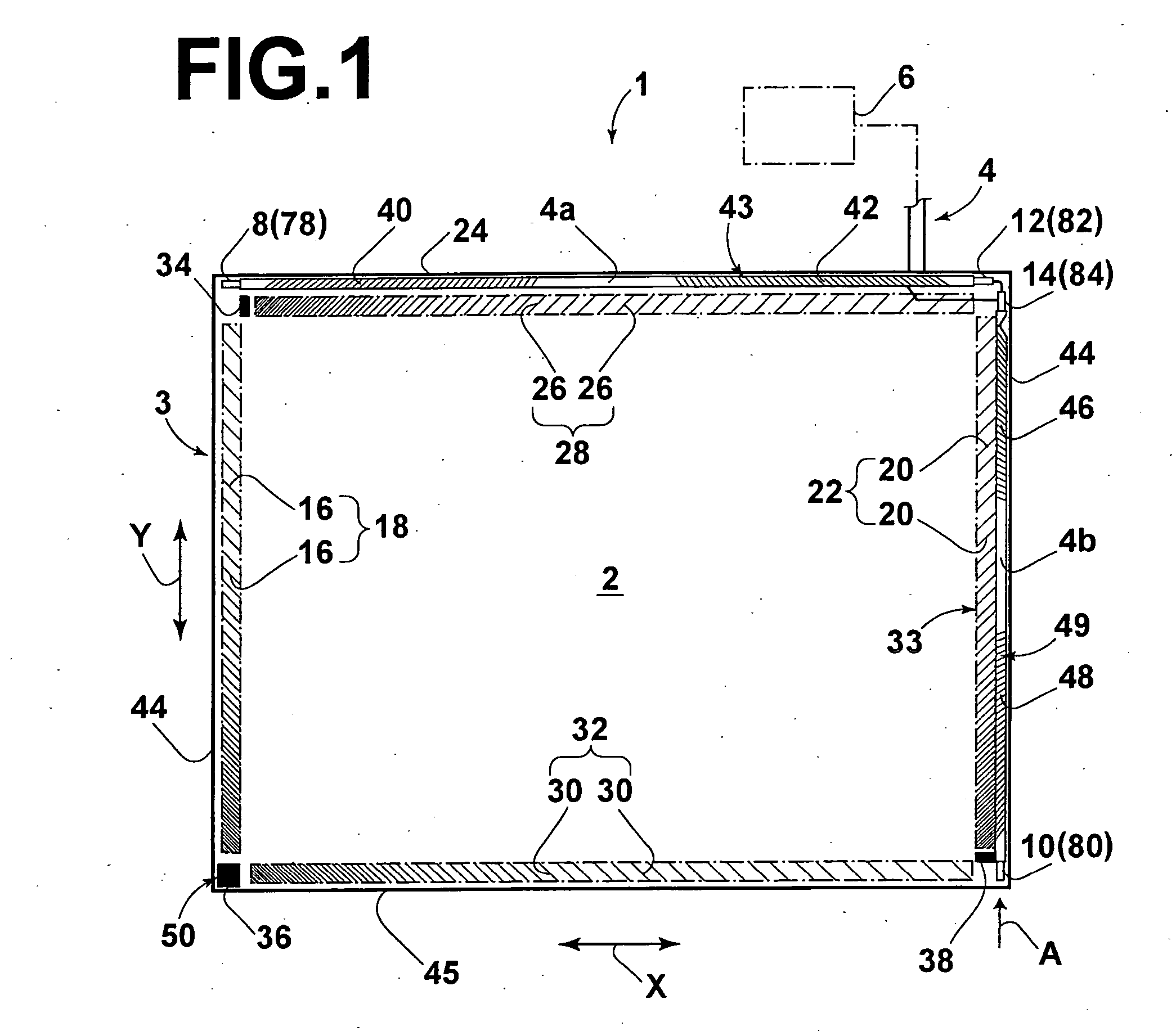
[0042]FIG. 1 is a front view of a touch panel 3, to be utilized in an apparatus 1. As shown in FIG. 1, the touch panel 3 comprises: a substrate 2 formed by a rectangular glass plate; a Flexible Printed Circuit 4 (FPC) mounted on the substrate 2; and a controller 6, which is electrically linked to the FPC 4.

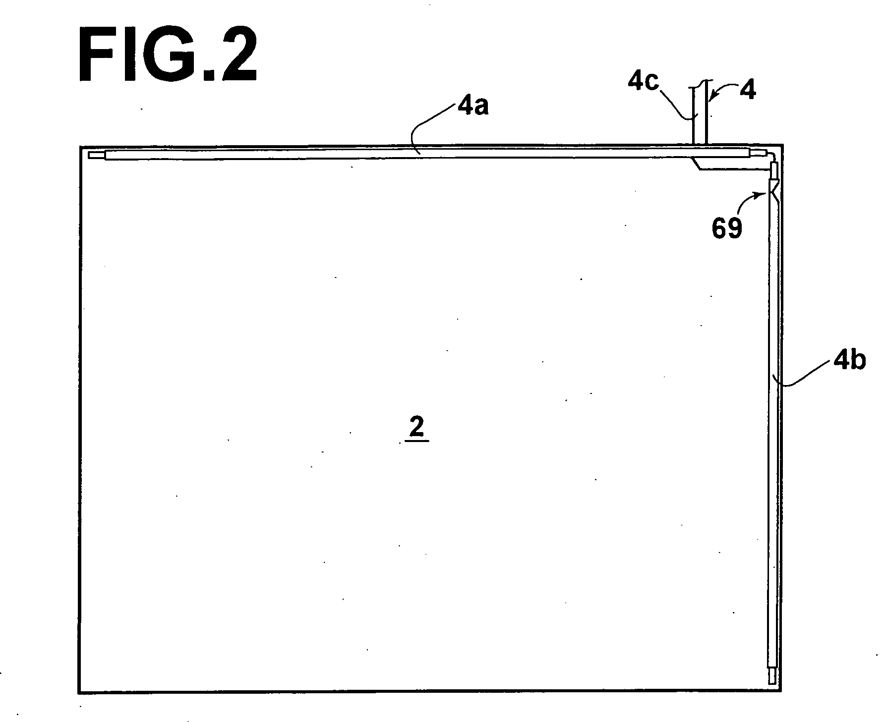
[0043] The FPC 4 is branched into an FPC branch 4a and an FPC branch 4b. The FPC branch 4a extends along the horizontal direction of the substrate 2, that is, the X axis direction indicated by the arrow X. The FPC branch 4b extends along the vertical direction of the substrate perpendicular to the X axis, that is, the Y axis direction indicated by the arrow Y. Converters (bulk wave generating means) 8 and 10 for generating ultrasonic waves are mounted on the FPC 4. In addition, converters (detecto...


PUM


Abstract

Two groups of inclined lines, which are included in a spurious wave scattering means, are formed at opposite angles with respect to each other in the vicinity of an upper edge of a substrate. The angles of the inclined lines are such that they are close to perpendicular toward the central portion of the substrate, and gradually decrease toward the edges thereof. In a similar manner, two other groups inclined lines, which are also included in the spurious wave scattering means, are formed at opposite angles with respect to each other, with gradually changing angles. The spurious waves that reach these regions are diffuse by the inclined lines, so that they are not propagated to converters (sensors). Three rectangular spurious wave scattering means, formed by inclined lines, inclined at angles other than 45°, also function to diffuse and eliminate spurious waves that propagate along the front surface of the substrate.

Description

BACKGROUND OF THE INVENTION [0001] 1. Field of the Invention [0002] The present invention relates to an acoustic wave contact detecting apparatus, such as an ultrasonic touch panel. [0003] 2. Description of the Related Art [0004] Ultrasonic acoustic wave contact detecting apparatuses are in widespread use. Examples of their applications include operating screens of personal computers, ticket dispensers at train stations, copiers installed in convenience stores, and ATM's at financial institutions. These acoustic wave contact detecting apparatuses utilize transducers, including piezoelectric vibrators (piezoelectric elements) provided on a substrate (touch panel) formed of glass or the like. These transducers function both as generating means for bulk waves and as sensors for detecting acoustic waves which are scattered by a finger or the like that contacts the touch panel. The surface acoustic waves are scattered by a finger or the like. The scattering of the surface acoustic waves ...

Claims


Application Information

Patent Timeline
Patent Type & Authority Applications(United States)
IPC IPC(8): G01B17/00G06F3/033G06F3/043
CPCG06F3/0436G06F3/03
Inventor TANAKA, YOSHIKAZUKENT, JOELRONEY, JAMES
Owner ELO TOUCH SOLUTIONS INC
Why Eureka
Try Eureka