Molded pump

a technology for pool pumps and injection molding, which is applied in the direction of pumping, positive displacement liquid engines, liquid fuel engines, etc., can solve the problems of inability to manufacture a commercial pool pump using the injection molding process, normal equipment that is required, and inability to remove facilities,

Inactive Publication Date: 2005-07-21
PENTAIR WATER POOL & SPA INC
View PDF17 Cites 29 Cited by
  • Summary
  • Abstract
  • Description
  • Claims
  • Application Information

AI Technical Summary

Problems solved by technology

Previously, manufacturing a commercial swimming pool pump using an injection molding process was not practical due the relatively small market size, the capital investment required, and the technical challenges involved in commercializing an injection molded pump of suitable size.
One disadvantage of commercial pumps is that they normally require special equipment such as a hoist or lift truck to install or replace the pumps.
This is especially important when replacing pumps in an existing installation where access by a lift truck is no longer practical without removing facility doors or walls.
Another disadvantage of commercial pumps is that they can be susceptible to corrosion, which can cause vital pump components to fail and ultimately shutting down the pump and the pool.
Furthermore, the corroding components can deposit permanent chemical stains on the pool walls.
Another disadvantage of cast pumps is that the cast components are cast to a rough size and finish.
Therefore, cast components require additional machining to shape and finish the components.
Still another disadvantage of cast pumps is the inherent defects that are present in the metal casting process.
These defects include pinholes, poor surface finish, and rapid surface oxidation.
Typically, cast components are reworked to repair these defects thereby adding cost to the manufacture of such pumps.
However, the costs associated with installing and maintaining multiple pumps were not cost effective.
In addition, one challenge in manufacturing large injection molded parts is the difficulty in molding an open end of a large cylindrical shaped part with a high degree of roundness.
Another challenge is that it is difficult to mold a flat plate type geometric shape such as a pump seal plate to a controlled tolerance of flatness.

Method used


Image

  • Molded pump
  • Molded pump
  • Molded pump

Examples


Embodiment Construction

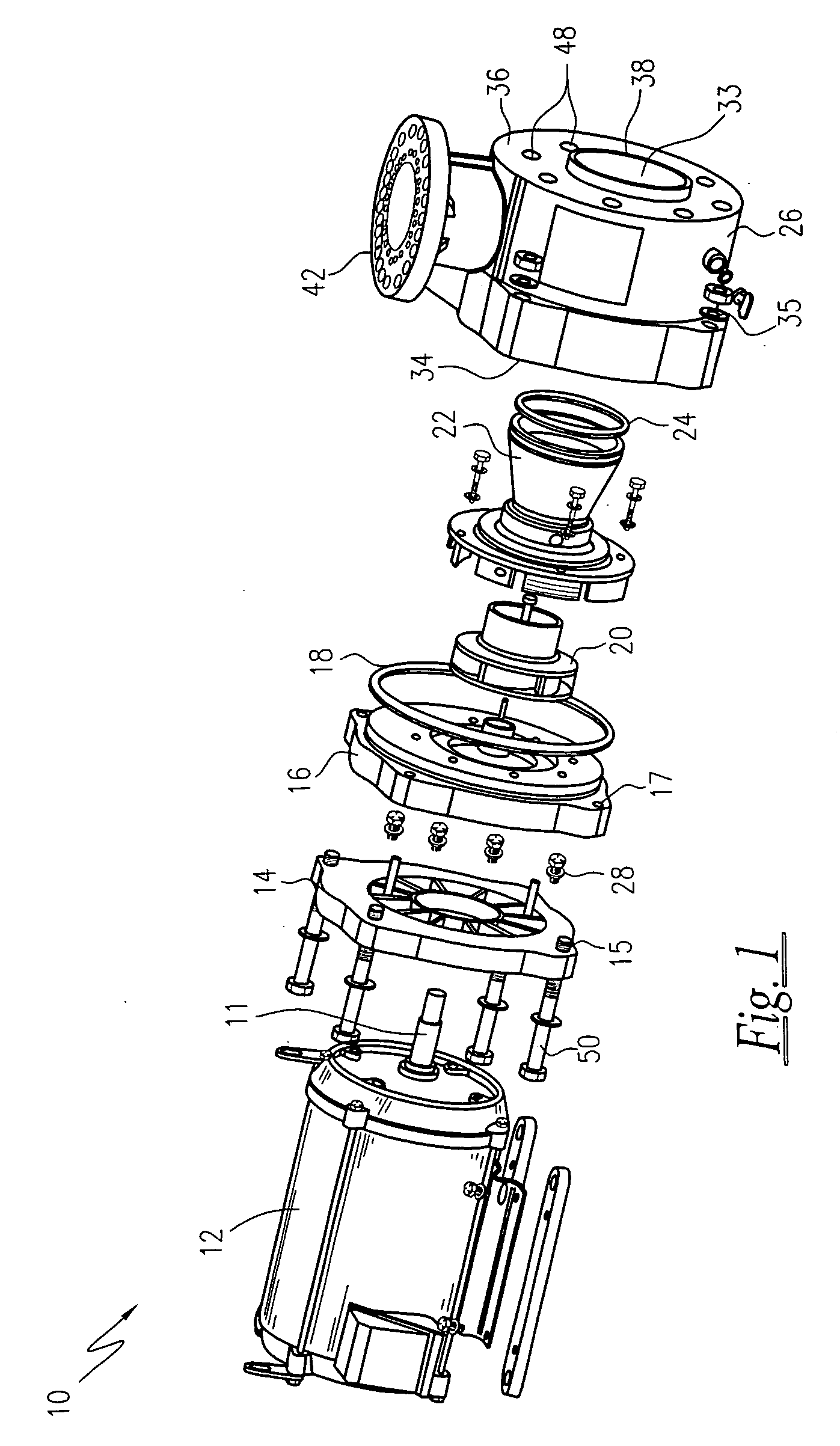
[0021] Referring now to the drawings, FIGS. 1 and 4 show two main assemblies of an injection molded pump. FIG. 1 shows a pump assembly 10 and FIG. 4 shows a modular pre-pump filter assembly 60. The pump assembly 10 will be subsequently described and the modular pre-pump assembly 60 will be described in detail further below.

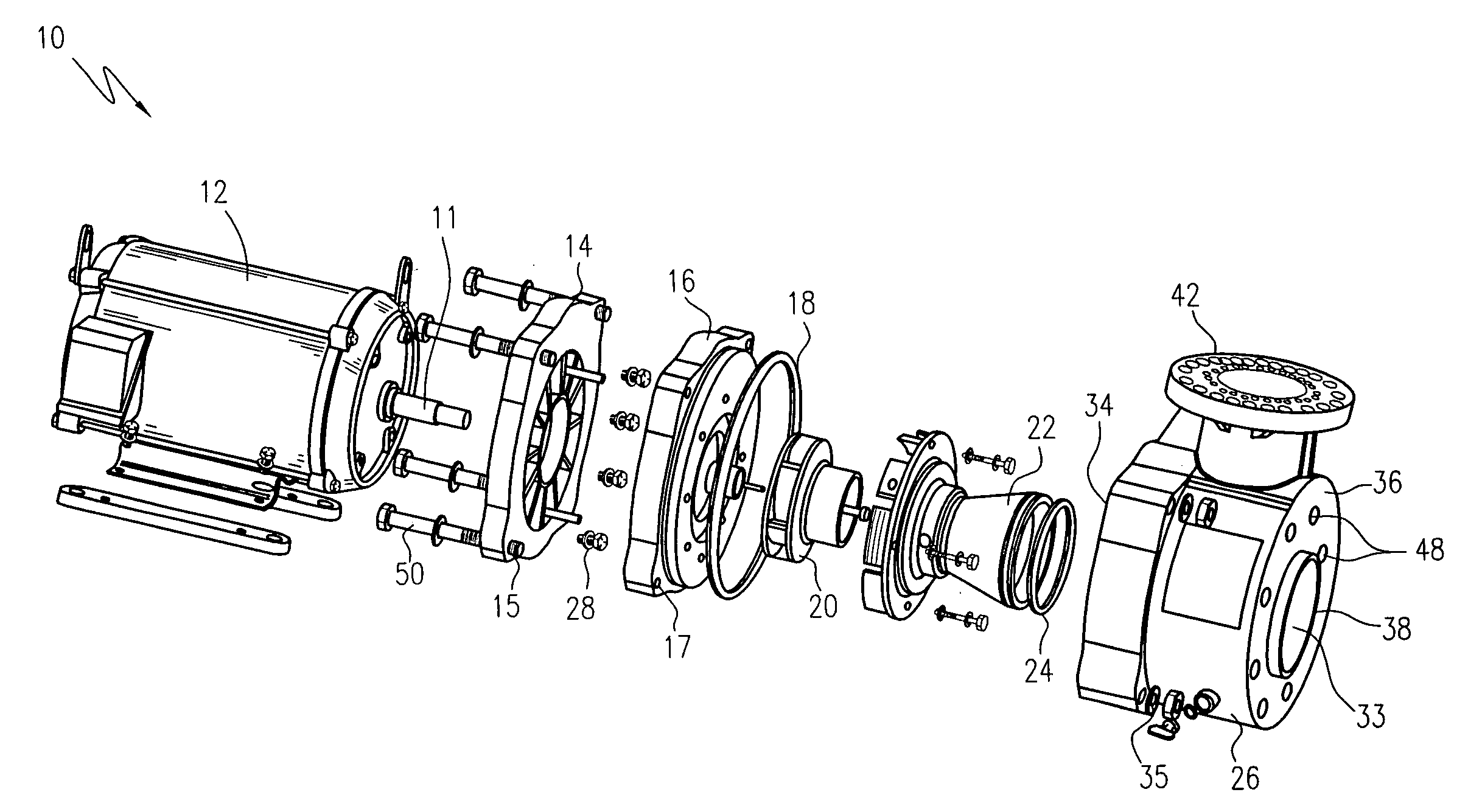
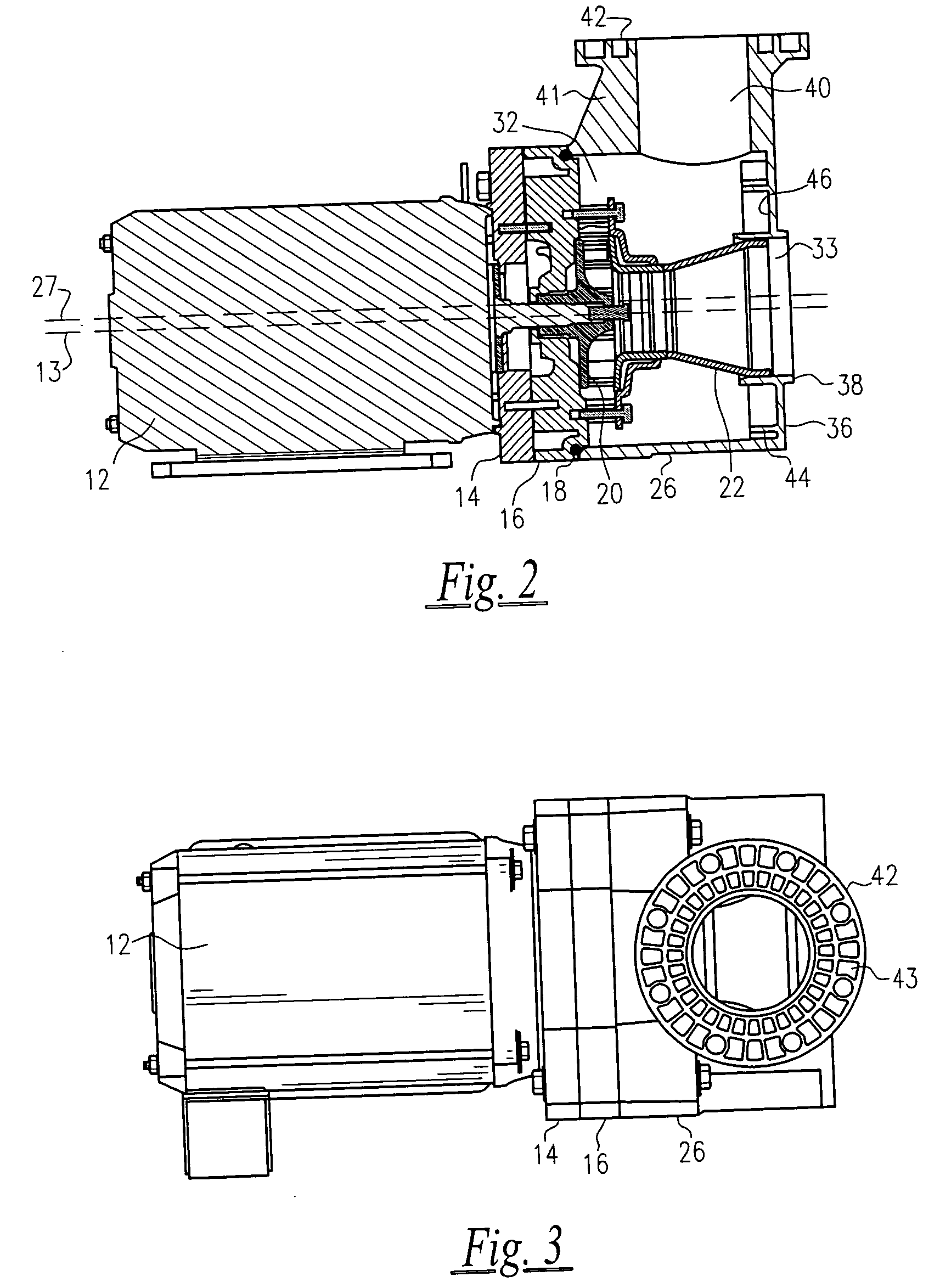
[0022] Referring to FIGS. 1-3, FIG. 1 shows an exploded view of the pump assembly 10. The main components of the pump assembly 10 include a motor 12 having a rotatable shaft 11, an adaptor plate 14, a seal plate 16, a seal plate o-ring 18, an impeller 20, a diffuser 22 adjacent to the impeller 20, a diffuser o-ring 24, and a pump housing 26. The motor 12 can be, for example, an electric motor having a suitable size and power such as many commonly known in the art and will not be described in further detail. The combination adapter plate 14 and seal plate 16 provide a unique seal arrangement to both increase strength and reduce stress between the pump housing 26 a...


PUM


Abstract

An injection molded commercial pool pump is provided having a motor, an adapter plate connected to the motor, a housing connected to the adapter plate further comprising a channel, a sealing plate positioned between the adapter plate and housing, an impeller connected to the motor shaft, an o-ring positioned between the sealing plate and housing to prevent leaking of internal fluids and a diffuser positioned over the impeller and connected to the sealing plate where the diffuser and impeller are inserted into the channel.

Description

[0001] This application claims the benefit of U.S. Provisional Patent Application No. 60 / 537,537 filed on Jan. 20, 2004.FIELD OF THE INVENTION [0002] The present invention relates to a commercial pool pump and more specifically to a partially injection molded pool pump assembly for use in large commercial pool applications. BACKGROUND OF THE INVENTION [0003] The commercial swimming pool pump market is defined by size, typically ranging from 5 HP to 25 HP. Previously, manufacturing a commercial swimming pool pump using an injection molding process was not practical due the relatively small market size, the capital investment required, and the technical challenges involved in commercializing an injection molded pump of suitable size. Commercial swimming pool pumps are typically constructed of either cast iron or cast bronze that weigh between 300-500 pounds. One disadvantage of commercial pumps is that they normally require special equipment such as a hoist or lift truck to install or...

Claims


Application Information

Patent Timeline
Patent Type & Authority Applications(United States)
IPC IPC(8): F04D9/02F04D29/02F04D29/62
CPCF04D9/02F04D29/708F04D29/628F04D29/026F05D2230/20F05D2300/43
Inventor SLOAN, JOANNE B.CHINTHANIPPULA, RAJAIAHSTOUT, DOUGLAS L.EDWARDS, DICK
Owner PENTAIR WATER POOL & SPA INC
Why Eureka
Try Eureka