Method for verifying position on an angioplasty balloon

a technology of angioplasty and position verification, which is applied in the direction of prosthesis, instruments, blood vessels, etc., can solve the problems of increasing the chance of stent failure, increasing the occurrence of stent failure, and increasing so as to reduce facilitate the determination. , the effect of reducing the failure rate of intraluminal grafts

Inactive Publication Date: 2005-07-21
MIRUS LLC
View PDF48 Cites 51 Cited by
  • Summary
  • Abstract
  • Description
  • Claims
  • Application Information

AI Technical Summary

Benefits of technology

[0019] Still a further and/or alternative object of the present invention is to facilitate in ensuring the use of high quality intraluminal grafts for insertion in a human or animal.
[0020] Yet a further and/or alternative object of the present invention is to reduce the failure rate of intraluminal grafts.
[0021] Still yet a furt

Problems solved by technology

If the angioplasty balloon is not properly positioned in the stent, the stent may not properly expand in the body cavity, thereby increasing the chances of stent failure.
The repositioning of the angioplasty balloon may result in the stent being improperly expanded in the body cavity, thereby increasing the chances of stent failure.
If the stent is to be crimped to form the body of the stent in a particular shape, the shape of the body of the stent must be correct after crimping to achieve the desired shape after expansion of the stent; otherwise, an improperly shaped expanded stent may increase the occurrence of stent failure.
If the stent is damaged, the stent may not properly expand in the body cavity, may break during expansion, may be structurally weakened, and/or the shape of the crimped stent may be adversely altered and interfere with the proper insertion of the stent into a body cavity.
A damaged and/or ad

Method used


Image

  • Method for verifying position on an angioplasty balloon
  • Method for verifying position on an angioplasty balloon
  • Method for verifying position on an angioplasty balloon

Examples


Embodiment Construction

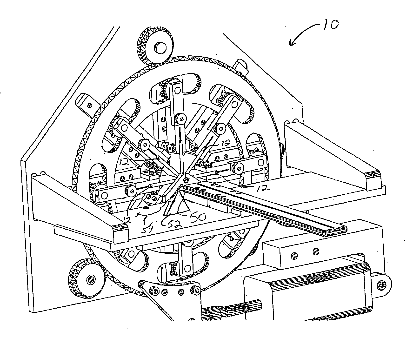
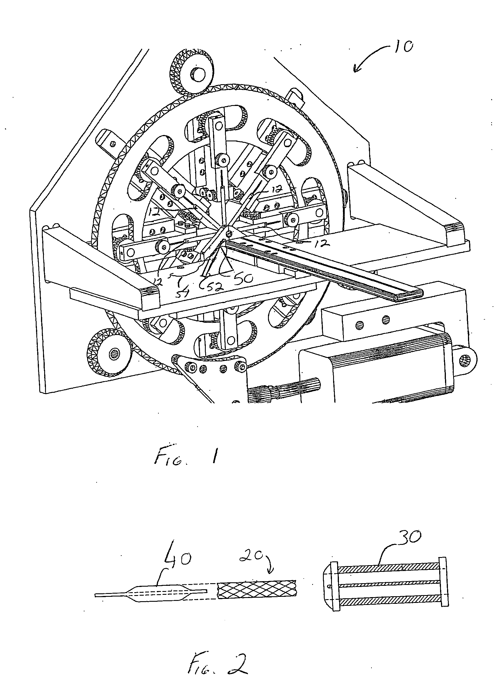
[0028] Stents and stent delivery assemblies are utilized in a number of medical procedures and situations, and as such their structure and function are well known. A stent is a generally cylindrical prosthesis introduced via a catheter into a lumen of a body vessel in a configuration having a generally reduced diameter and then expanded to the diameter of the body cavity such as, but not limited to, a blood vessel. In its expanded configuration, the stent supports and reinforces the body cavity walls while maintaining the body cavity in an open, unobstructed condition. Expandable stents are well known and widely available in a variety of designs and configurations. Expandable stents are commonly crimped to their reduced diameter about the delivery catheter, then maneuvered to the deployment site and expanded to the body cavity diameter by fluid inflation of a balloon that is typically positioned between the stent and the delivery catheter. The present invention is particularly direc...


PUM


Abstract

A monitoring system and data archive system for a stent crimping process. The information concerning the crimped stent is used in deciding whether the stent is acceptable for insertion into the body cavity of a human or animal.

Description

[0001] The present invention claims priority on U.S. Provisional Patent Application Ser. No. 60 / 536,777 filed Jan. 15, 2004 entitled “Method for Verifying Drug Coated Stent Apposition on an Angioplasty Balloon Before and After Crimping”, which is incorporated by reference herein. [0002] The present invention relates to intraluminal grafts and particularly to coated or non-coated intraluminal grafts that are modified in shape such as, but not limited to, crimping. INCORPORATION BY REFERENCE [0003] United States Patent Publication No. 2003 / 0040790 entitled Stent Coating and 2002 / 0099438 entitled Irradiated Stent Coating, and U.S. Pat. No. 6,436,133 entitled Expandable Graft and U.S. Pat. No. 6,206,916 entitled Coated Intraluminal Graft, and PCT Publication No. WO 03 / 037398 entitled Improved Stent Coating are incorporated herein by reference. U.S. Pat. Nos. 5,860,966; 5,893,852; 5,893,867; 5,911,752; 5,931,851; 5,951,540; 5,992,000; 6,009,614; 6,024,737; 6,033,380; 6,051,002; 6,063,092...

Claims


Application Information

Patent Timeline
IPC IPC(8): A61F2/06A61F2/84
CPCA61F2/958A61F2250/0085A61F2002/9522A61F2/9522
Inventor FURST, JOSEPH G.BRODBECK, WILLIAM
Owner MIRUS LLC
Why Eureka
Try Eureka