
Method and controller for the adaptive control of at least one component of a technical plant

Inactive Publication Date: 2005-07-21
SIEMENS AG
View PDF10 Cites 4 Cited by
  • Summary
  • Abstract
  • Description
  • Claims
  • Application Information

AI Technical Summary

Benefits of technology

[0008] The object of the invention is therefore to specify an improved method and a controller for controlling at least one component of a technical plant. This should in particular overcome the described disadvantages from prior art. Furthermore, a control method in accordance with the invention and a controller in accordance with the invention should reduce the cost of setting the controller parameters. Furthermore, a method in accordance with the invention and a controller in accordance with the invention should enable a particularly simple start-up of a component to be controlled.
[0016] Investigations of controlled systems have shown that setting the integral-action time control parameter in advance is usually adequate to achieve a good, desired control behavior of the controlled system. It is thus not necessary to also continuously change the integral-action time control parameter in order to achieve a good control result during the operation of the technical plant. The advantage of this is mainly that the controlled system dynamics, e.g. for further investigations or test purposes, are easier to describe and model, because due to the integral-action time being specified in advance, the dynamic behavior of the PI controller does not change and a suitable, for example mathematical, description of the controlled system can easily be given and used.
[0018] The system time constants of a system to be controlled influence the speed with which the system reacts to a change of at least one of its input signals by changing at least one of its output signals. Almost any practical control system is subject to a delay, as it is called, and thus also includes at least one system time constant in its corresponding mathematical model equation. For example a controlled system that can be described by a third order mathematical order equation includes three system time constants. Knowledge of the values of the system time constants for a controlled system under consideration enables the delay of the controlled system to be well estimated.
[0020] In many practical cases that occur, tests have shown that a multiple with a value of approximately 1.5 produces good results, i.e. that the integral-action time of the PI controller in such cases is to be set to a value corresponding to one and half times the sum of the system time constants. Furthermore, multiples with a value of approximately 0.7 also produce good results, i.e. the integral-action time of PI controller in such cases is to be advantageously set to a value corresponding to 70% of the sum of the system time constants. When doing so, however, it is to be noted that the effect of the amount of integral action of the PI controller reduces with increasing value of the named multiple.
[0022] With this form of embodiment, oscillations in the time response of the actual value in particular should be detected, in particular displaying themselves in that the actual value assumes a value within the tolerance band during the control action once again and subsequently enters and leaves the tolerance band. The dwell time is now determined during which the oscillating actual value moves within the tolerance band before it leaves it once again. The shorter this dwell time the faster the actual value changes relative to time, so that in a case of this kind the control ratio of the PI controller is to be reduced in order to leave the actual value within the tolerance band during the operation of the technical plant. If the dwell time is less than the first defined time period, an excessive oscillation of the actual value (the actual values goes “too fast” through the tolerance band) is assumed and the control ratio is reduced thus preventing an intolerable oscillation of this kind of the actual value beyond the limits of the tolerance band.

Problems solved by technology

However, the use of parameter values set in advance for the PI controller is not always the optimum solution, particularly for the control of power station plants, because in the course of time during the operation of the power station plant the dynamic behavior of the technical process effected by the components of the technical plant can change.
Thus, after a change of this kind in the dynamic behavior of the components the controller parameters set in advance are no longer optimum for the new operating conditions now present and under certain circumstances can even lead to failure of the control system, so that the desired control effect can no longer be achieved.
For example, after a change in the dynamic behavior of the controlled system (components) and thus the control circuit formed by the components and the PI controller, the actual value of the control variable can have a tendency towards unwanted oscillations during the control action that can lead to instability of the controlled system.
Apart from the fact that a controlled circuit of a technical plant that has become functionally unserviceable can be hazardous to operators and potentially damaging to machines, particularly if a control system that has become unstable creates corrections that are too great and / or actual values of the control variable that are far too large, and because of the downtime required to repair the control system a production failure of the technical plant is practically unavoidable.
If the technical plant is a power station, the failure of a component of the technical plant can, for example, jeopardize the supply of electrical power to an area.
The use of constant values for the PI controller leads to problems, particularly where used for control in power stations with a steam process, because in power stations of this kind the control systems to be controlled often have a non-linear behavior.
Thus if there is an unavoidable shift in the working point of a non-linear components to be controlled or the technical plant during operation of the technical plant, the preset controller parameters are possibly no longer suitable for the new operation point (working point) for producing the desired control effect.
This can even have the effect that a PI controller has an optimum control behavior for an operating point of the component, but results in completely inadequate or even dangerous control outcomes when a changeover to a new operating point occurs.

Method used


Image

  • Method and controller for the adaptive control of at least one component of a technical plant
  • Method and controller for the adaptive control of at least one component of a technical plant
  • Method and controller for the adaptive control of at least one component of a technical plant

Examples


Embodiment Construction

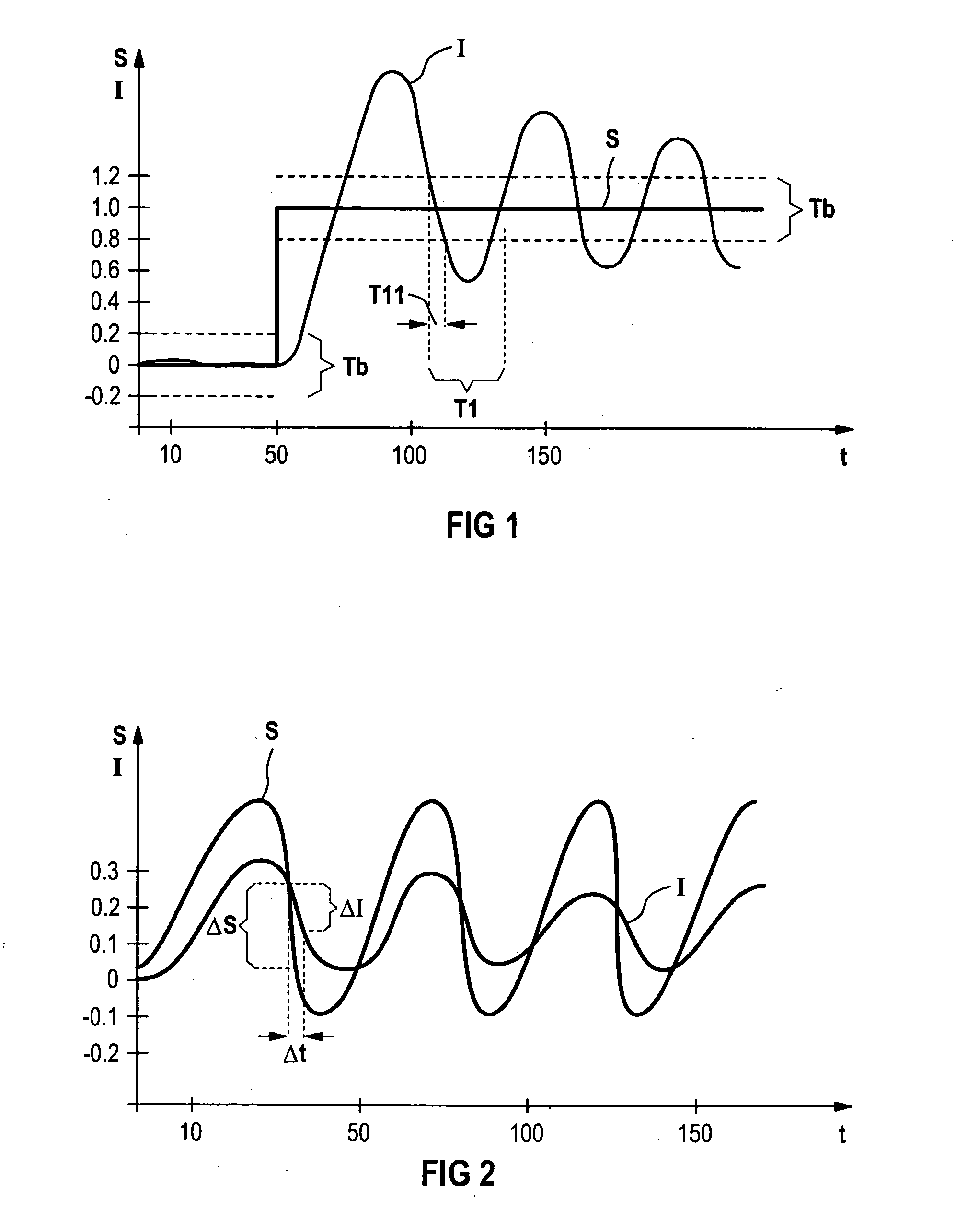
[0046]FIG. 1 show an example of the time response of an actual value I, that has an oscillation and even over a long time period does not satisfactorily approximate to a defined set value S, and thus in particular does not move within a tolerance band Tb.

[0047] The illustration in FIG. 1 shows the time behavior of the set and actual values of a controlled component of a technical plant. At time point t=50 (for example t=50 sec.), the set value S changes suddenly from S=0 to S=1 and remains constant from time point t=50. With a controlled system, it is desirable for the actual value I of the associated control variable to follow the time response of the set value S as closely as possible, whereby on one hand the set value S should be reached as quickly as possible and on the other hand excessive over- or undershoots of the actual value I relative to the set value S must be avoided in order to obtain a stable controlled system. In particular, oscillations of the actual value I that d...


PUM


Abstract

The invention relates to a method in which at least one component of a technical plant is controlled by means of a PI controller. The actual value of the regulating parameter is continuously determined during operation of the plant and the amplification factor of the PI controller is altered depending on the time relationship of the actual value, until the actual value remains with a tolerance band relative to the set value. The invention further relates to a controller for carrying out said method.

Description

CROSS REFERENCE TO RELATED APPLICATION [0001] This application is the US National Stage of International Application No. PCT / DE03 / 00793, filed Mar. 12, 2003 and claims the benefit thereof. The International Application claims the benefits of German Patent application No. 10213533.9 DE filed Mar. 26, 2002, both of the applications are incorporated by reference herein in their entirety.FIELD OF THE INVENTION [0002] The invention relates to a method for controlling at least one component of a technical plant, and a corresponding controller. BACKGROUND OF THE INVENTION [0003] The starting point is a conventional control concept according to which a control variable of a component of the technical plant is held as closely as possible to the set value of the control variable by means of a PI controller. To do so, the PI controller determines a correction action for an actuator assigned to one of the components from the difference between the set value and actual value of the control varia...

Claims


Application Information

Patent Timeline
IPC IPC(8): G05B11/42G05B13/02
CPCG05B13/024G05B11/42
Inventor HAGUET, MAGALIEWENDELBERGER, KLAUS-WALTER
Owner SIEMENS AG
Learn More