Gas turbine power generator plant and silencer for the same

a technology of generator plant and silencer, which is applied in the direction of electric generator control, machines/engines, mechanical equipment, etc., can solve the problem of emitted loud noise toward the outside of the case, and achieve the effect of reducing noise and further reducing nois

Inactive Publication Date: 2005-07-28
HITACHI LTD
View PDF11 Cites 50 Cited by
  • Summary
  • Abstract
  • Description
  • Claims
  • Application Information

AI Technical Summary

Benefits of technology

[0031] Furthermore, the duct of the intake silencer is bent substantially at a right angle, sound absorbers are provided on both sides of the insides of the divided combustion air channels of the duct, and the surfaces of both these sound absorbers are shaped in matching concave and convex with substantially equal distances between them, noise can be further reduced.
[0032] Since according to the invention the duct constituting the combustion air channel is bent substantially at a right angle, the duct on the downstream side with respect to the noise source is divided by the partitioning plate into two combustion air channels and the route length of each combustion air channel is differentiated, the sound absorbers are provided on both sides of the insides of the divided combustion air channels of the duct, and the surfaces of both these sound absorbers are shaped in matching concave and convex with substantially equal distances between them, it is made possible to provide a gas turbine power generator plant which can reduce noise in not only a wide band from low frequency to high frequency but also in a specific frequency band.

Problems solved by technology

Whereas the above patent publication disclosed noise reduction by the use of a soundproof enclosure, it is apt to emit loud noise toward the outside of the case because the case has a common intake for the air for combustion use by the gas turbine and the air for cooling the turbine engine and therefore a large opening is formed in the case.

Method used


Image

  • Gas turbine power generator plant and silencer for the same
  • Gas turbine power generator plant and silencer for the same
  • Gas turbine power generator plant and silencer for the same

Examples


Embodiment Construction

[0045] A gas turbine power generator plant according to one embodiment of the invention will be described by using drawings.

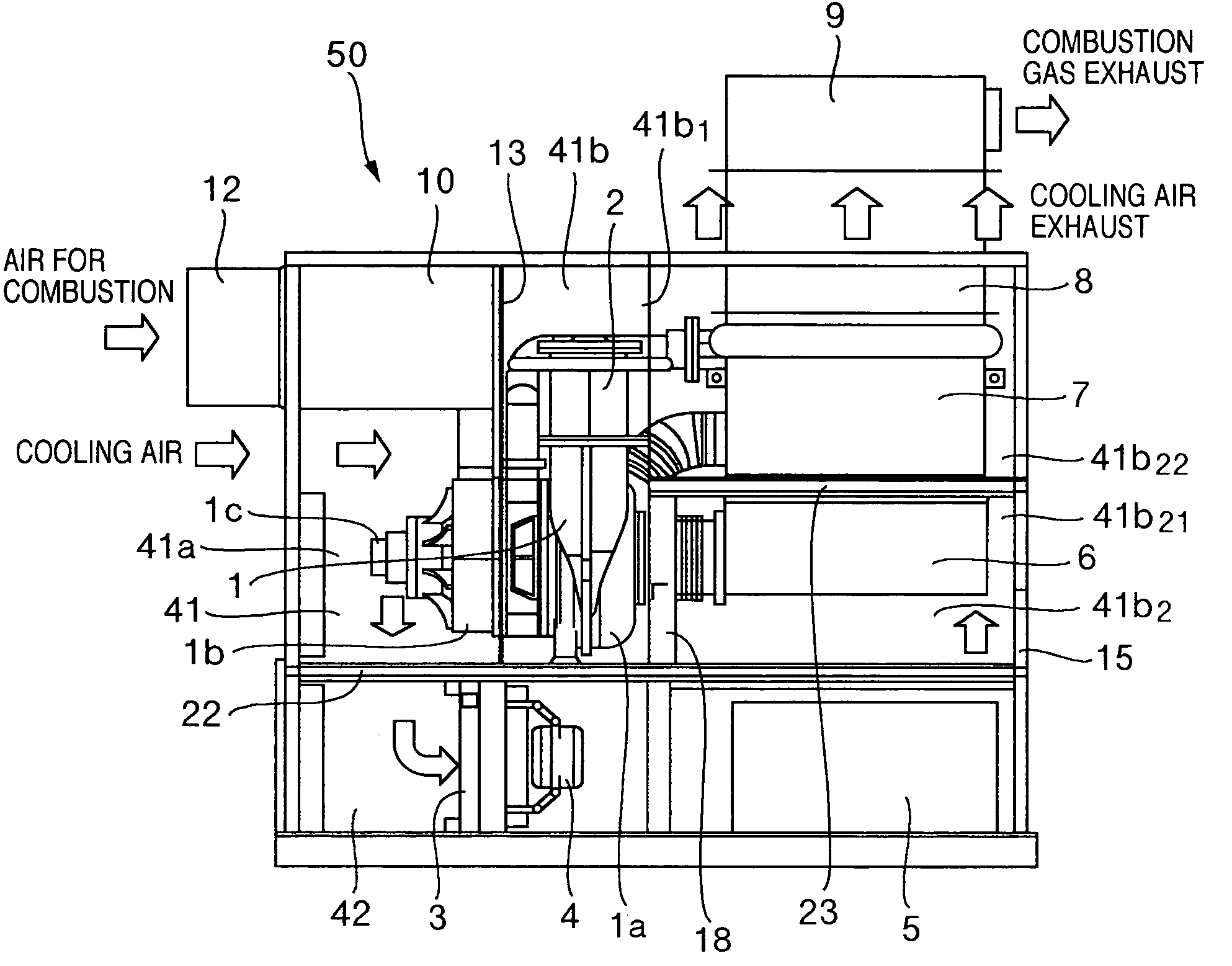
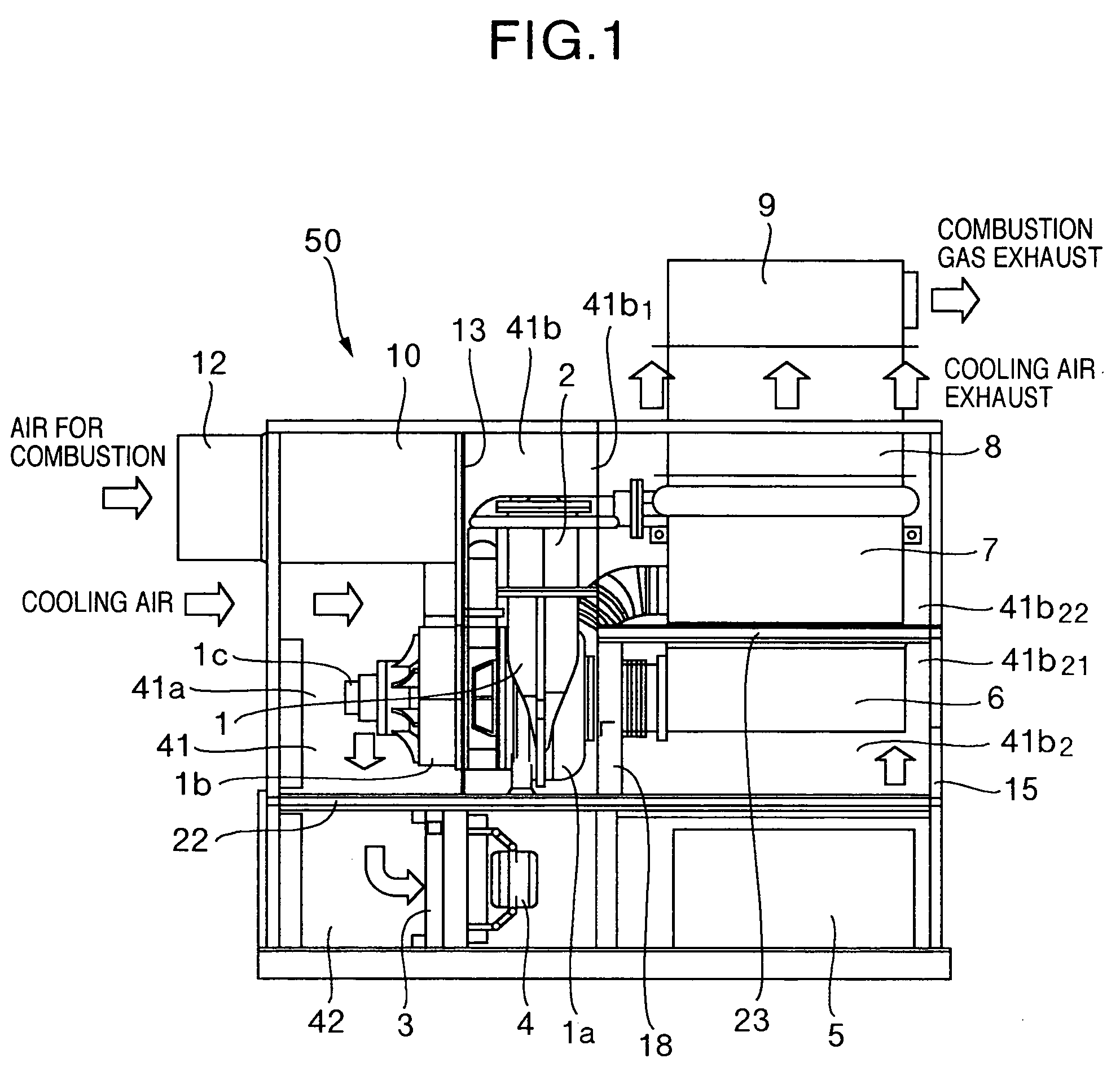
[0046] First, a gas turbine power generator plant 50 in this embodiment will be described with reference to FIG. 1 through FIG. 4. FIG. 1 is a schematic vertical section view of a gas turbine power generator plant according to one embodiment of the invention; FIG. 2, a left side profile of the embodiment in FIG. 1; FIG. 3, a perspective view of the casing by itself of the gas turbine power generator plant in FIG. 1; and FIG. 4, a plan view of the engine core base of the case in FIG. 3. Incidentally, FIG. 3 shows the case in a state in which a front board is removed.

[0047] The gas turbine power generator plant 50, as shown in FIG. 1, has a configuration mainly having within a case 15 an engine core 1, a combustor 2, a radiator 3, a cooling fan 4, an electric power converter 5, an exhaust duct 6, and a regenerative heat exchanger 7. The radiator 3 is installed ...


PUM


Abstract

A gas turbine power generator plant, intended to reduce its noise by making small the intake and exhaust outlets of the cooing air channel of a case, comprises an engine core in which a turbine, a compressor and a generator are installed on the same axis, a combustor for burning air for combustion compressed by the compressor and supplying the air to the turbine, a radiator for cooling a coolant or a lubricant, a cooling fan for ventilating the radiator with cooling air, an electric power converter for converting electric power generated by the generator, and the case for housing these constituent elements. And, a combustion air channel passing the compressor, the combustor and the turbine and a cooling air channel passing the radiator, the cooling fan and the electric power converter are formed as mutually independent channels from intake to exhaust.

Description

BACKGROUND OF THE RELATED ART [0001] The present invention relates to a gas turbine power generator plant and a silencer for use in the same. DESCRIPTION OF THE RELATED ART [0002] Among conventional silencers for gas turbines, there is one described in JP-A-2002-242698. The configuration of this silencer comprises a soundproof enclosure having an air inlet opening in its front wall and a closed space formed inside, a gas turbine which is disposed within the soundproof enclosure and to which is connected an exhaust pipe for discharging exhaust gas outside the soundproof enclosure, a plurality of silencing splitter pipes arranged within the soundproof enclosure and close to the gas turbine to form inside an air intake silencing gap communicating with both ends of which one faces the air intake opening side and the other is terminated facing a rear wall opposite the front face, a sound-absorbing exhaust passage which is connected to an air exhaust opening disposed in the soundproof enc...

Claims


Application Information

Patent Timeline
Patent Type & Authority Applications(United States)
IPC IPC(8): F01D25/12F01D25/00F01D25/24F01D25/30F02C6/00F02C7/00F02C7/045F02C7/14F02C7/18F02C7/20F02C7/24F02C7/32H02P9/04
CPCF02C7/12F05D2260/96F02C7/32
Inventor NAKANO, SUSUMUICHINOSE, MASAYAWATANABE, MASANORITSUBOUCHI, KUNIYOSHIFUKUSHIMA, TOSHIHIKOWATANABE, MASATOSHI
Owner HITACHI LTD
Why Eureka
Try Eureka