

Clock generating device, vibration type gyro sensor, navigation device, imaging device, and electronic apparatus
a clock generation device and vibration type gyro technology, applied in the field of clock generation devices, can solve the problems of limited device miniaturization and increase manufacturing costs, and achieve the effects of suppressing the large size of imaging devices, increasing manufacturing costs, and reducing the size of imaging devices
- Summary
- Abstract
- Description
- Claims
- Application Information
AI Technical Summary
Benefits of technology
Problems solved by technology
Method used
Image

Examples
first embodiment
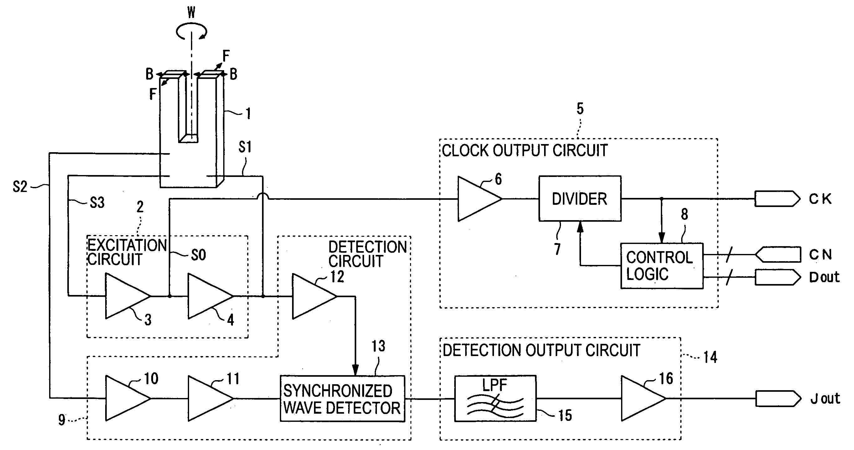
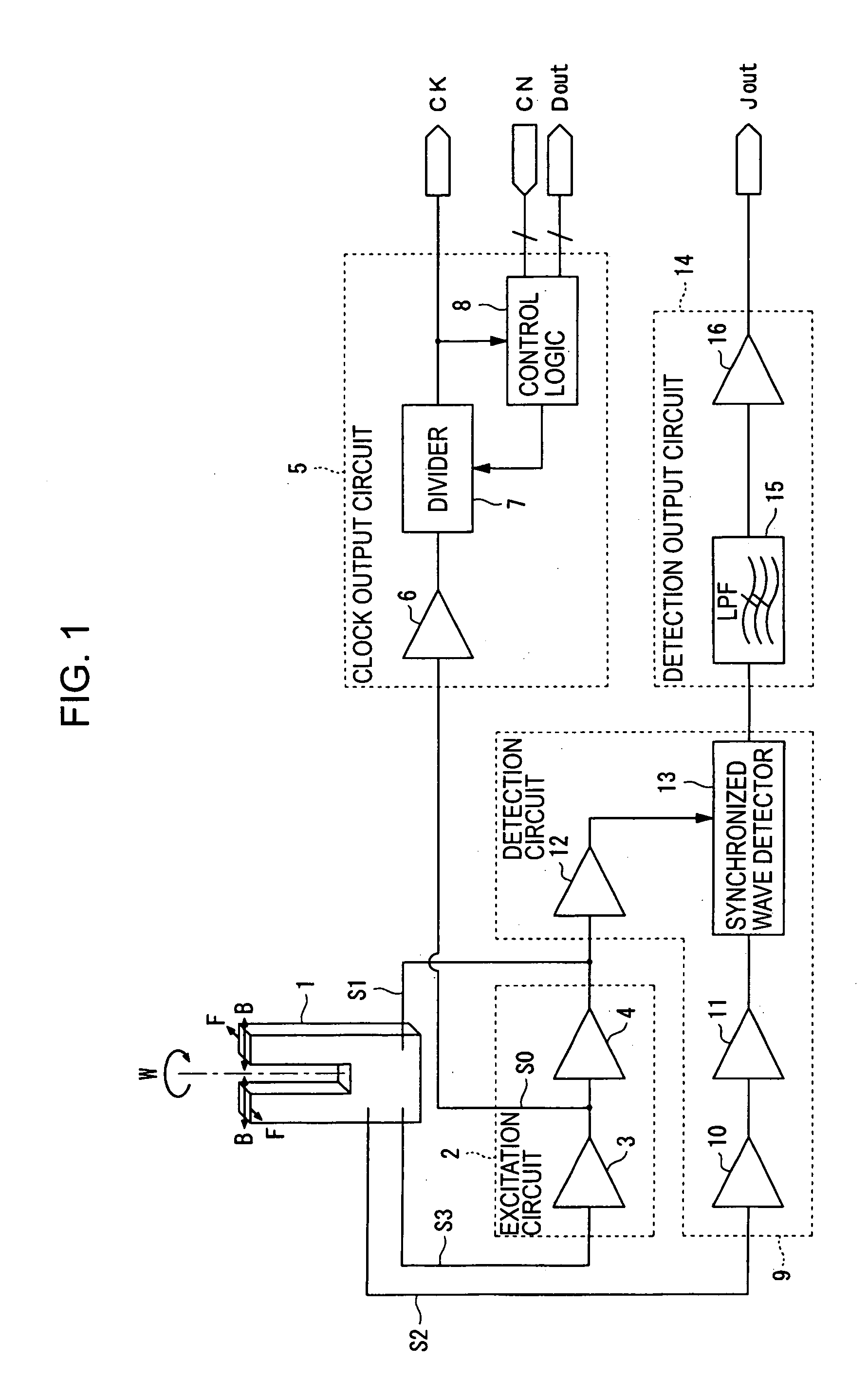
[0044]FIG. 1 is a block diagram showing a configuration of a vibration type gyro sensor according to the present invention.
[0045] Referring to FIG. 1, the vibration type gyro sensor has a tuning fork piezoelectric vibrating reed 1, an excitation circuit 2 for exciting the tuning fork piezoelectric vibrating reed 1, a detection circuit 9 for detecting a coriolis force F acting on a vibration B when the tuning fork piezoelectric vibrating reed 1 rotates at an angular velocity (, a detection output circuit 14 for generating an angular velocity signal Jout based on an output from the detection circuit 9, and a clock output circuit 5 for generating a timer clock signal based on an excitation signal S0 which excites the tuning fork piezoelectric vibrating reed 1.
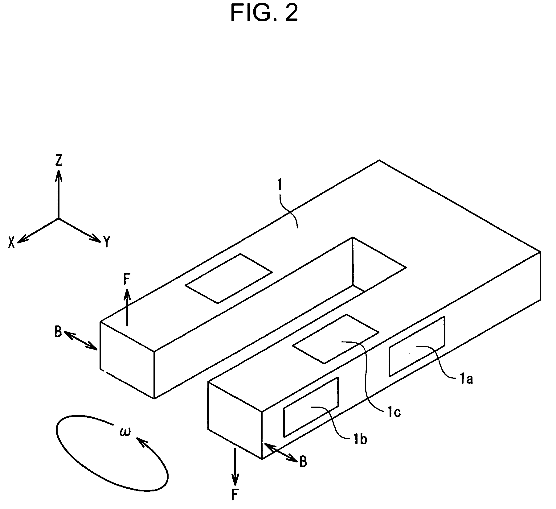
[0046]FIG. 2 is a perspective view schematically showing a configuration of the tuning fork piezoelectric vibrating reed 1 shown in FIG. 1.
[0047] Referring to FIG. 2, for example, the tuning fork piezoelectric vibrating reed 1 i...
second embodiment
[0060]FIG. 3 is a block diagram showing a configuration of a vibration type gyro sensor according to the present invention.
[0061] Referring to FIG. 3, instead of the detection circuit 9 and the detection output circuit 14 shown in FIG. 1, a detection circuit 9′ and a detection output circuit 14′ are provided. Then, in the detection circuit 9′, instead of the IV conversion amplifier 10, the AC amplifier 11, the right angle phase shifter 12, and the synchronized wave detector 13 shown in FIG. 2, an IV conversion amplifier 10′, an AC amplifier 11′, a right angle phase shifter 12′, and a synchronized wave detector 13′ are provided. Further, in the detection output circuit 14′, instead of the low pass filter 15 and the output amplifier 16 shown in FIG. 2, a low pass filter 15′ and an output amplifier 16′ are provided.
[0062] In this case, the IV conversion amplifier 10′, the AC amplifier 11′, the right angle phase shifter 12′, the synchronized wave detector 13′, the low pass filter 15′, ...
third embodiment
[0064]FIG. 4 is a block diagram schematically showing a configuration of a navigation device according to the present invention.
[0065] Referring to FIG. 4, the navigation device comprises a position detector 21 for detecting its own position, a map data acquiring unit 26 for acquiring map data of a predetermined area, an operating switch 27 for performing various operations of the navigation device, a display device 29 capable of displaying its own current position on the map to overlap, and a control circuit 28 for performing an overall control of the above-mentioned devices having been associated with each other.
[0066] Further, the position detector 21 has a GPS receiver 23, a vibration type gyro sensor 24, and a distance sensor 25, and the GPS receiver 23 has an antenna 22 for receiving electrical waves from a GPS satellite, and a satellite tracking unit 23a for tracking the GPS satellite which is used to receive a GPS signal at the time of positioning.
[0067] In this case, the ...
PUM
 Abstract
Description
Claims
Application Information