Pedal force detection device

a detection device and pedal technology, applied in the direction of mechanical control devices, instruments, force/torque/work measurement apparatus, etc., can solve the problems of unintentional pedal depressing by the driver, insufficient transmission of pedal force to the load detection unit, and inability to detect the force of the pedal sufficiently, so as to reduce the breakage of the pedal, the load is larger, and the detection accuracy of the pedal is improved.

Inactive Publication Date: 2005-07-28
DENSO CORP
View PDF7 Cites 9 Cited by
  • Summary
  • Abstract
  • Description
  • Claims
  • Application Information

AI Technical Summary

Benefits of technology

[0009] According to the present invention, in a pedal force detection device, a load sensor (load detection unit) is provided with a matrix made of a ceramics having a large pressure-withstanding strength, so that a small-sized load sensor can be used while satisfactory detection accuracy can be maintained.
[0012] Preferably, each of the connecting portion and the first and second arms has larger stiffness in other directions different from that of the resilient deformation thereof due to the pedal force, respectively. Therefore, a resilient deformation as well as a breakage of the pedal arm unit in the other directions can be restricted, thus improving the detection accuracy of the pedal force.
[0015] Preferably, the first arm has an end portion which is apart from the pedal and adjacent to the parallel portion. The end portion is bent to the side of the second arm 4. The second arm 4 is connected to the end portion near a position between the end portion and the parallel portion. Between the second arm and the parallel portion of the first arm, the load sensor is inserted. Thus, when the force is exerted on the pedal, the first arm has a larger deformation to exert a larger load on the load sensor. Therefore, the detection accuracy of the pedal force can be improved.
[0016] Preferably, the pedal force detection device further includes at least a base member having a convex portion and disposed between the load sensor and at least one of the first and second arms. The base member is capable of transmitting the load. At least the one of the first and second arms has a concave portion to contact the convex portion of the base member, so that a surface contact is provided therebetween. Accordingly, stress concentration in the base member and the first and second arms due to a point contact can be restricted, thus diminishing a breakage thereof.

Problems solved by technology

On the other hand, when the force is smaller than or equal to the predetermined value, it is determined that the driver depresses the pedal unintentionally.
However, in this case, a sliding friction between a push rod and a wall of the housing of the load detection unit will generate a hysteresis between the output of the load detection unit and the pedal force, so that the detection accuracy is decreased.
In this case, when the pedal is intermittently depressed to exert an intermittent load on the isolation unit, a creep of the resin will occur to form a gap between the load detection unit and the isolation unit, so that the pedal force cannot be sufficiently transmitted to the load detection unit.
Therefore, the pedal force cannot be determined accurately and stably.
As a result, a large pressing force will be applied on the small-sized load detection unit, and thus shortening the lifetime thereof.

Method used


Image

  • Pedal force detection device
  • Pedal force detection device
  • Pedal force detection device

Examples


first embodiment

[0043] A pedal force detection device of the present invention according to the first embodiment will be described with reference to FIGS. 1-10.

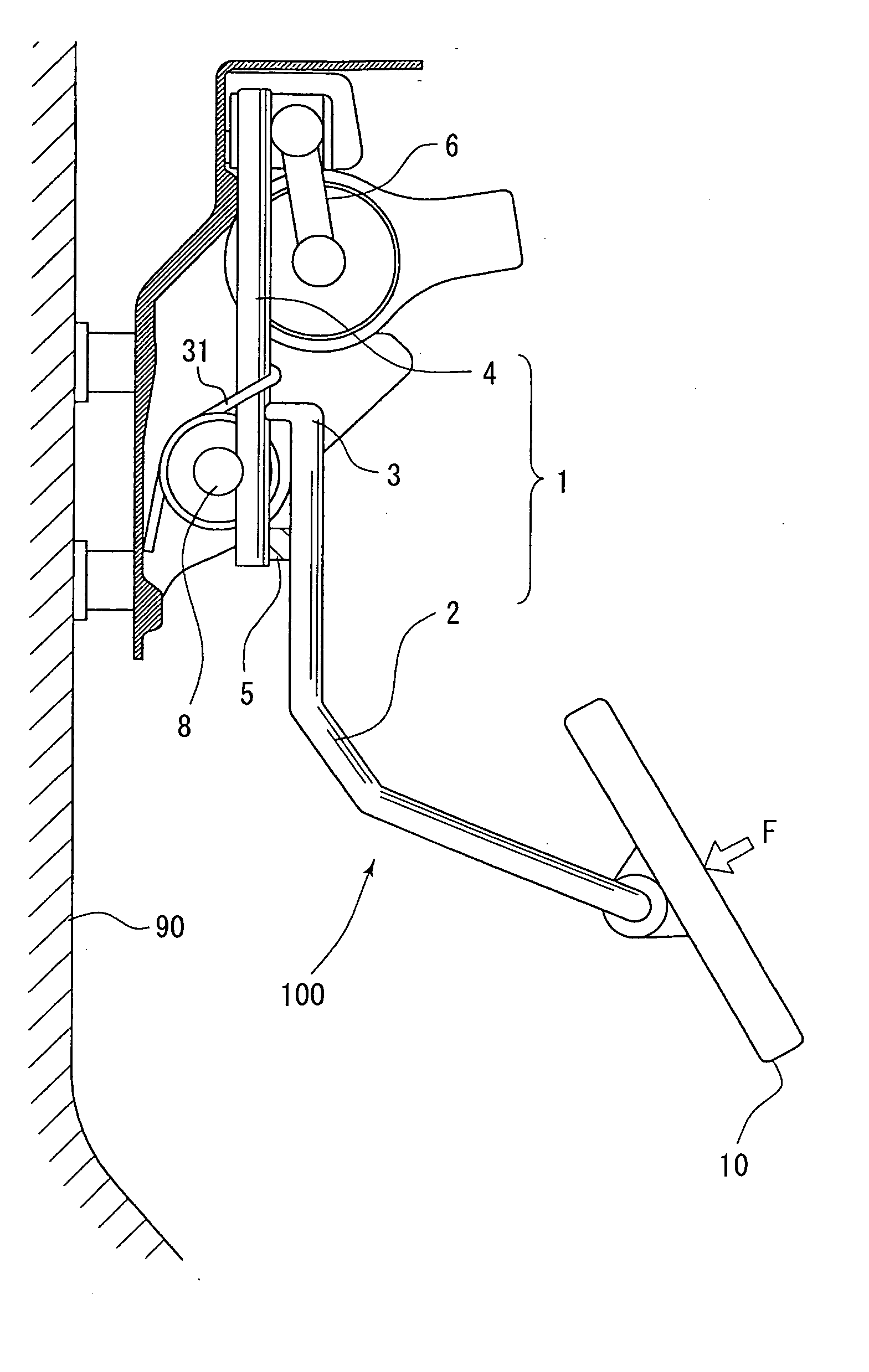
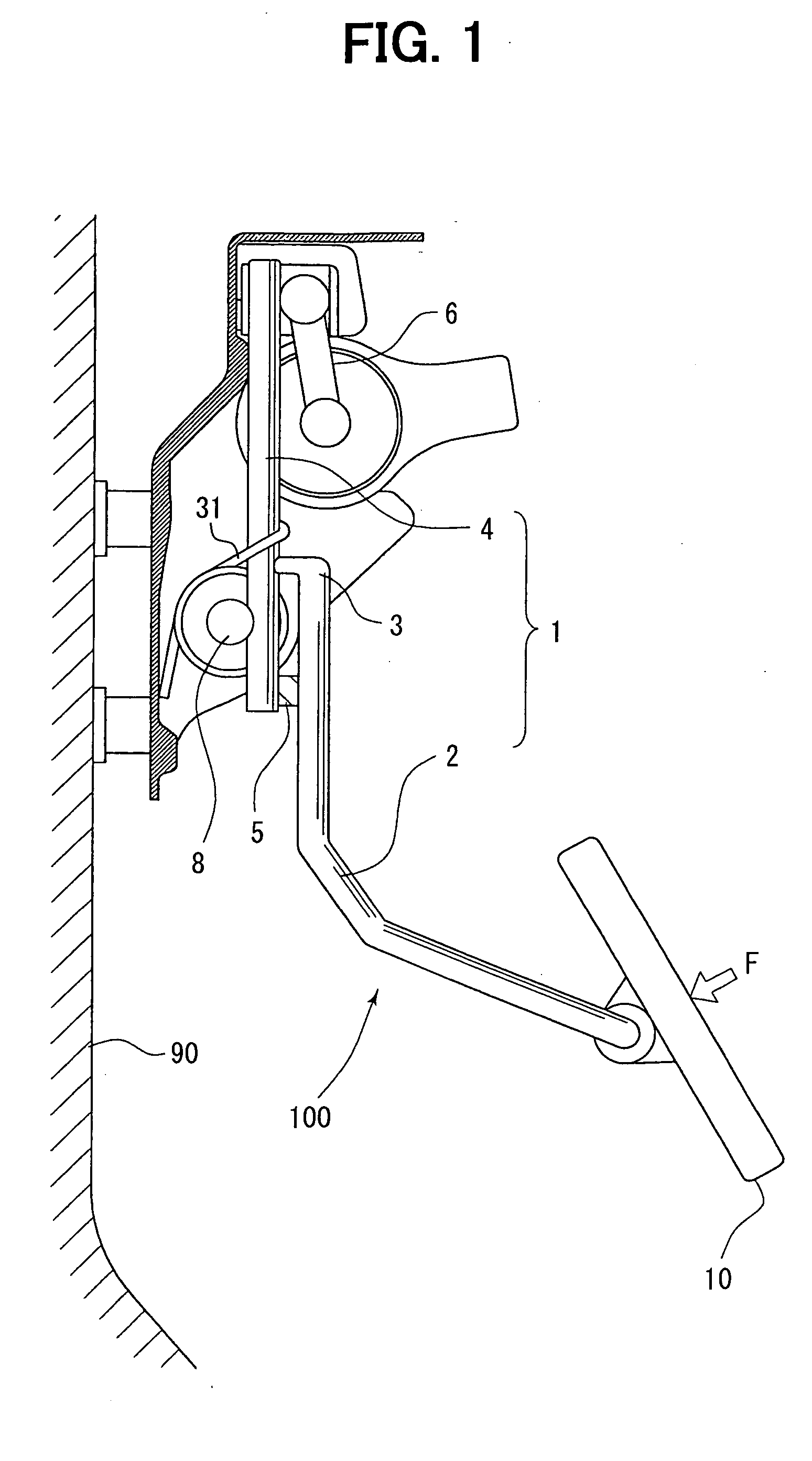
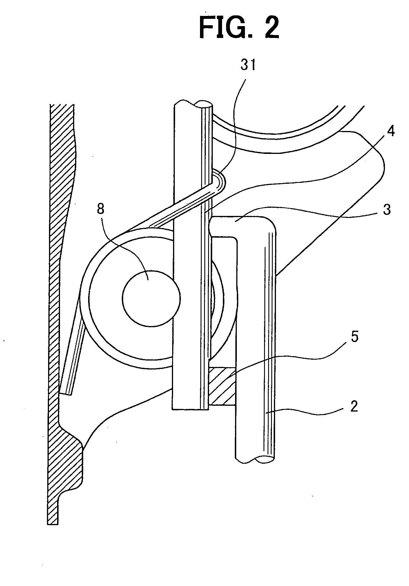
[0044] The pedal force detection device includes a pedal arm unit 1 and a load sensor 5, and is arranged in a pedal assembly 100, which is fixed to a vehicle chassis 90, as shown in FIG. 1. The pedal arm unit 1 is provided with a first arm 2 at which a pedal 10 is mounted, a second arm 4 rotatably supported by a rotational support 8 and a connecting portion 3 which connects the first arm 2 to the second arm 4. The pedal 10 is depressed by a force which has a component force F perpendicular to the surface of the pedal 10. The load sensor 5 is inserted in a gap between the first arm 2 and the second arm 4 for determining the force F.

[0045] As shown in FIG. 1, a stroke sensor 6 is provided for the pedal assembly 100 at an upper portion of the second arm 4, and interlocked with the second arm 4 to detect a rotation displacement thereof. The st...

second embodiment

[0063] In the above-described first embodiment, the load sensor 5 is inserted between the first arm 2 and the second arm 4. In the second embodiment referring to FIGS. 11-15, the pedal force detection device is provided with a load detection unit 50 sandwiched in the pedal arm unit 1, which is made of a resin and integrally formed.

[0064] In a pedal assembly 100 shown in FIG. 11, the whole pedal arm unit 1 is integrally formed without the first arm 2 and the second arm 4. The pedal arm unit 1 has ribs 11, each of which extends in a direction perpendicular to a central axis of the pedal arm unit 1. The pedal 10 is also integrated with the pedal arm unit 1 at one end of the pedal arm unit 1. The other end of the pedal arm unit 1 is rotatablely supported by the rotational support 8. The biasing unit (not shown) such as the return spring is attached to the pedal arm unit 1 to provide a resistance against the rotation thereof. Thus, the pedal arm unit 1 can be maintained at the initial p...

third embodiment

[0069] According to the above-described first embodiment, the rotational support 8 is attached to the second arm 4 to support the pedal arm unit 1. In the third embodiment as shown in FIGS. 16 and 17, both the first arm 2 and the second arm 4 are supported by the rotational support 8. Thus, the rotation of the pedal arm unit 1 will not be influenced even if the second arm 4 has a breakage. FIG. 16 shows the pedal assembly 100, in which the pedal force detection device including the pedal arm unit 1 and the load sensor 5 is mounted.

[0070] As shown in FIG. 17, the pedal arm unit 1 including the first arm 2 and the second arm 4 is mounted at the rotational support 8, which is rotatably supported by an attachment portion 91 fixed to the vehicle chassis 90. The first arm 2 is sequentially constructed with a pedal end portion 2g, a curve portion 2a, a parallel portion 2f, a bend portion 2b, a connection portion 2c and an insert end portion 2e. The pedal 10 is mounted at the pedal end 2g,...


PUM

PropertyMeasurementUnit
stress concentrationaaaaaaaaaa
forceaaaaaaaaaa
stiffnessaaaaaaaaaa

Abstract

In a pedal force detection device, a pedal arm unit is provided with a first arm at which a pedal is mounted, a second arm apart from the pedal and a connection portion for connecting the first and second arms. A load sensor having a matrix made of a ceramics is fixed between the first and second arms. When the pedal is depressed by a pedal force, the first arm approaches the second arm due to a resilient deformation so that the load sensor is compressed by a load. Thus, the pedal force can be determined based on the load detected by the load sensor.

Description

CROSS REFERENCE TO RELATED APPLICATION [0001] This application is based on Japanese Patent Applications No. 2004-19814 filed on Jan. 28, 2004 and No. 2004-336559 filed on Nov. 19, 2004, the disclosure of which are incorporated herein by reference.FIELD OF THE INVENTION [0002] The present invention relates to a pedal force detection device for detecting a force exerted on a pedal in a vehicle. BACKGROUND OF THE INVENTION [0003] Generally, an electronic throttle control device is used in a vehicle for controlling an opening degree of a throttle valve and an injection amount of fuel and the like, based on an electrical signal corresponding to a depression amount of an accelerator pedal. The pedal is mounted at a pedal arm rotatably supported by a rotation support, to which a rotation sensor is attached for detecting a rotation displacement of the rotation support. Thus, the depression amount of the pedal can be determined based on the detected rotation displacement. [0004] In this case...

Claims


Application Information

Patent Timeline
Patent Type & Authority Applications(United States)
IPC IPC(8): G01L1/04B60T7/02G01L1/20G01L5/22G05G1/00G05G1/30G05G1/38G05G1/44
CPCF02D2200/602G01L1/044G01L1/20G05G1/506G05G1/30G05G1/38G05G1/44G01L5/225
Inventor HAYAKAWA, HIDEYUKIMORIKAWA, KENJIIMAMURA, TETSUO
Owner DENSO CORP
Why Eureka
Try Eureka