Bonding of strain gauges to the deformable body of a force-measuring cell

a force-measuring cell and strain gauge technology, applied in the field of force-measuring cells, can solve the problems of so-called thermal stress building up in the installed strain gauge, and achieve the effects of reducing the number of strain gauges

Active Publication Date: 2005-07-28
METTLER TOLEDO GMBH
View PDF4 Cites 30 Cited by
  • Summary
  • Abstract
  • Description
  • Claims
  • Application Information

AI Technical Summary

Benefits of technology

[0026] The application of the inorganic-organic hybrid polymer materials in solution on the deformable body can be performed by the tampon-printing technique. This allows adhesive layers to be applied with a defined uniform thickness that is constant over the area of the strain gauge. Uniformity of the adhesive layer can be desired to achieve a fav...

Problems solved by technology

The drawbacks associated with the use of this adhesive material and the method of bonding the strain gauge to the deformable body are that on the one hand the deformable body will during the exposure to the increased temperature in t...

Method used


Image

  • Bonding of strain gauges to the deformable body of a force-measuring cell
  • Bonding of strain gauges to the deformable body of a force-measuring cell
  • Bonding of strain gauges to the deformable body of a force-measuring cell

Examples


Embodiment Construction

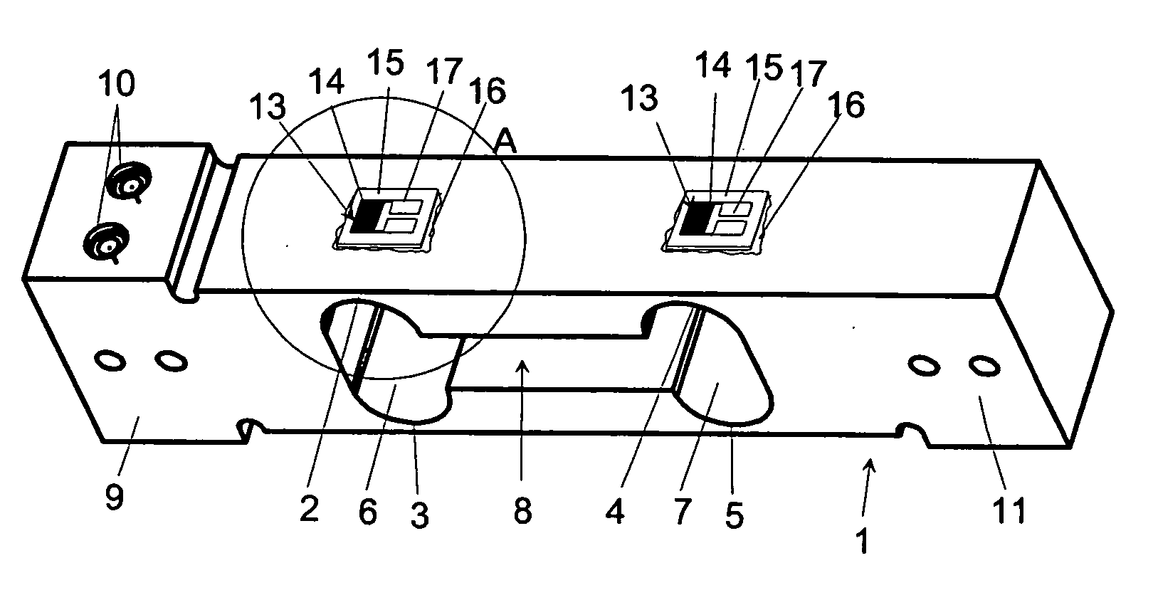
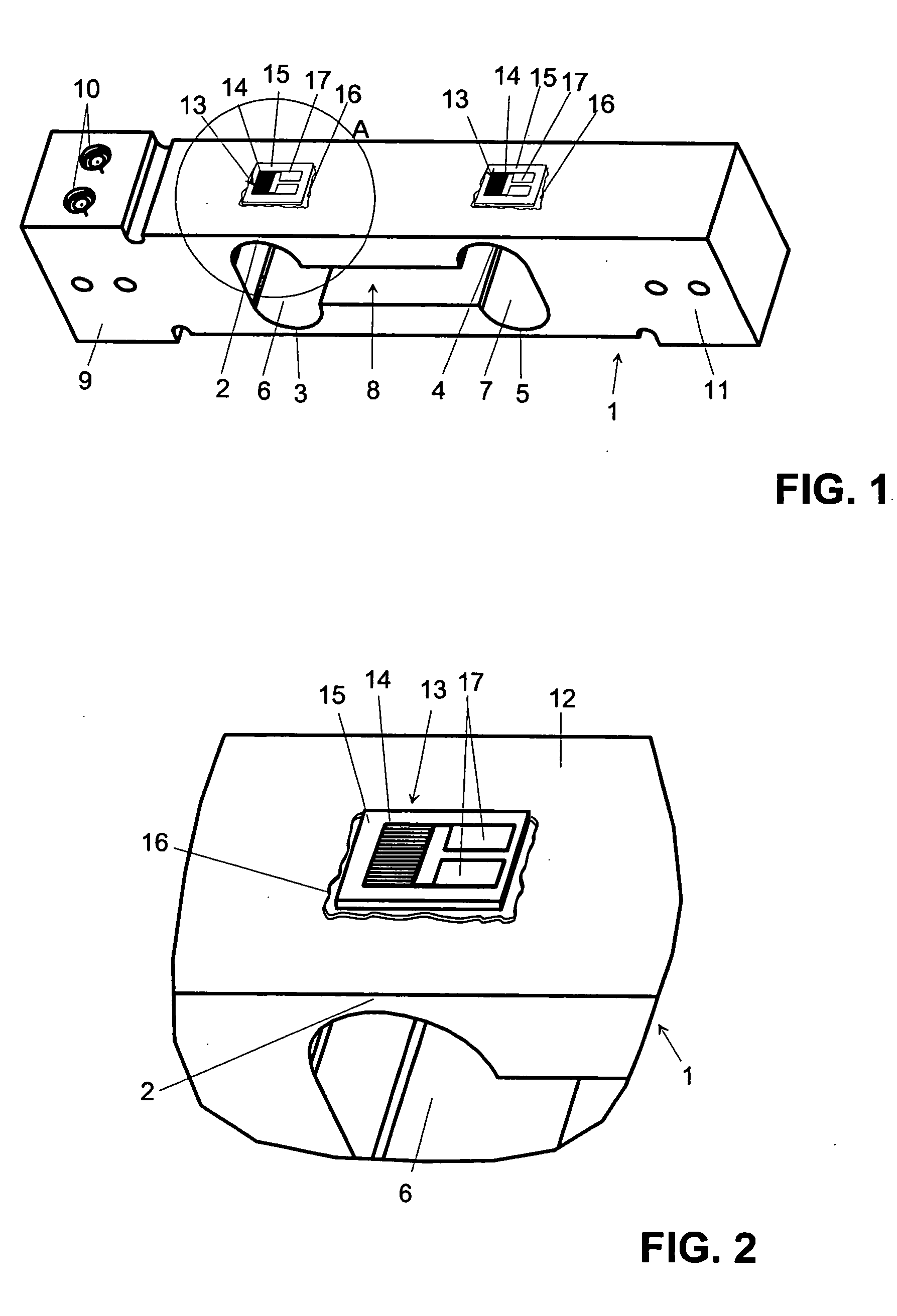
[0032]FIG. 1 illustrates an exemplary deformable body 1 of a weighing cell with four elastic bending zones 2, 3, 4, 5 arranged at the corner points of a parallelogram. The bending zones 2, 3, 4, 5 are formed by the curved contours of widened end portions 6, 7 of a cutout 8 at the center of the monolithic deformable body 1. The load receiver 9 of the deformable body 1, which is shown in the left-hand part of FIG. 1, is vertically movable. If a load is put on a weighing pan, which is not shown in the drawing but can be fastened by means of several screws to the tapped holes 10 of the load receiver 9, the load receiver 9 is moved vertically downward in relation to a stationary part 11 (shown in the right-hand part of the drawing) of the deformable body 1 which is fastened directly to a housing or to an intermediate mounting bracket, as the bending zones 2, 3, 4 and 5 undergo a deformation. This deformation is measured by means of strain gauges 13 that are adhesively bonded to the top s...


PUM


Abstract

In a force-measuring cell with a deformable body and with at least one strain gauge which has a strain-sensitive electrical resistor track arranged on a polymer carrier substrate, the strain gauge is bonded to the deformable body by an adhesive layer of an inorganic-organic hybrid polymer. For the bonding of the strain gauge to the deformable body, an adhesive compound having an inorganic-organic hybrid polymer in solution is applied to the deformable body, whereupon the strain gauge is placed on the hybrid polymer layer, and the adhesive layer is subsequently hardened at a temperature between 80° C. and 130° C. For the hardening of the adhesive layer, the deformable body with the strain gauge is exposed to the increased temperature for a time period between a half hour and three hours.

Description

RELATED APPLICATIONS [0001] This application claims benefit to European Priority Patent Application Serial Number 04 075 198.4, filed Jan. 27, 2004. This priority application is hereby incorporated by reference in its entirety. BACKGROUND [0002] 1. Field [0003] A force-measuring cell with a deformable body is disclosed, with at least one strain gauge installed on the deformable body by an adhesive layer, wherein the at least one strain gauge has a strain-sensitive electrical resistor track arranged on a carrier substrate. A method of bonding a strain-gauge to a deformable body is also disclosed. [0004] 2. Background Information [0005] A strain gauge has a carrier substrate on which a metallic resistor track is arranged which can be made in the shape of a meandering structure by a known chemical etching method. Also arranged on the carrier substrate are connector electrodes for contacting the resistor track. The connector electrodes are often made in one work operation together with ...

Claims


Application Information

Patent Timeline
IPC IPC(8): G01G3/14G01L1/22
CPCG01L1/2287G01G3/1402
Inventor TELLENBACH, JEAN-MAURICEZIEBART, VOLKER
Owner METTLER TOLEDO GMBH
Why Eureka
Try Eureka