Ballast system for tension leg platform

a technology of ballast tank and leg platform, which is applied in the direction of underwater equipment, special-purpose vessels, vessel construction, etc., can solve the problems of high-capacity requirements, and achieve the effect of rapid flooding of ballast tanks and achieving installation dra

Inactive Publication Date: 2005-07-28
SEA ENG ASSOCS +1
View PDF7 Cites 11 Cited by
  • Summary
  • Abstract
  • Description
  • Claims
  • Application Information

AI Technical Summary

Problems solved by technology

However, once installation is complete, only minor in-service trim adjustments are made, so the pumps are no longer subjected to high-capacity requirements.

Method used


Image

  • Ballast system for tension leg platform
  • Ballast system for tension leg platform
  • Ballast system for tension leg platform

Examples


first embodiment

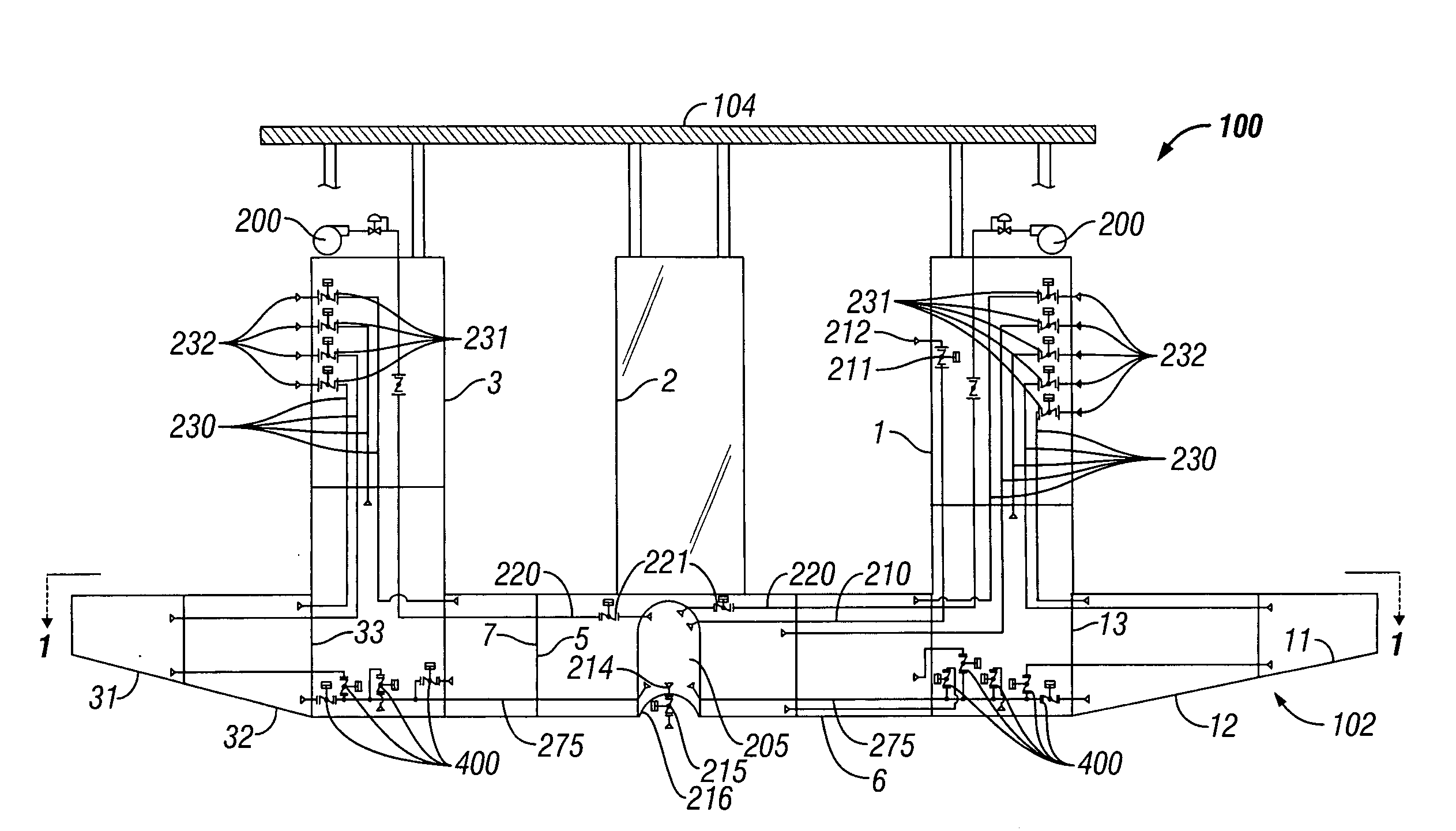
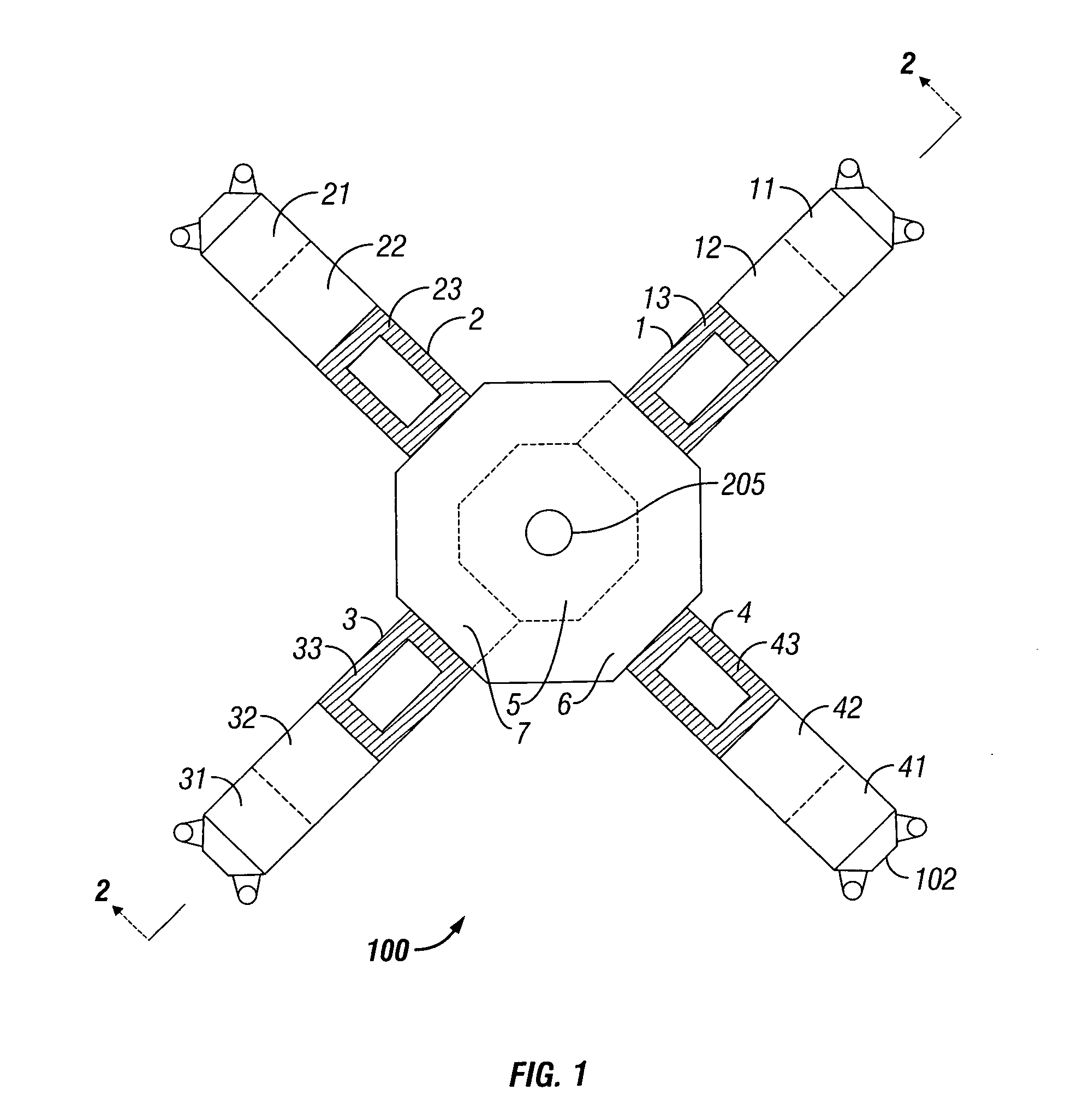
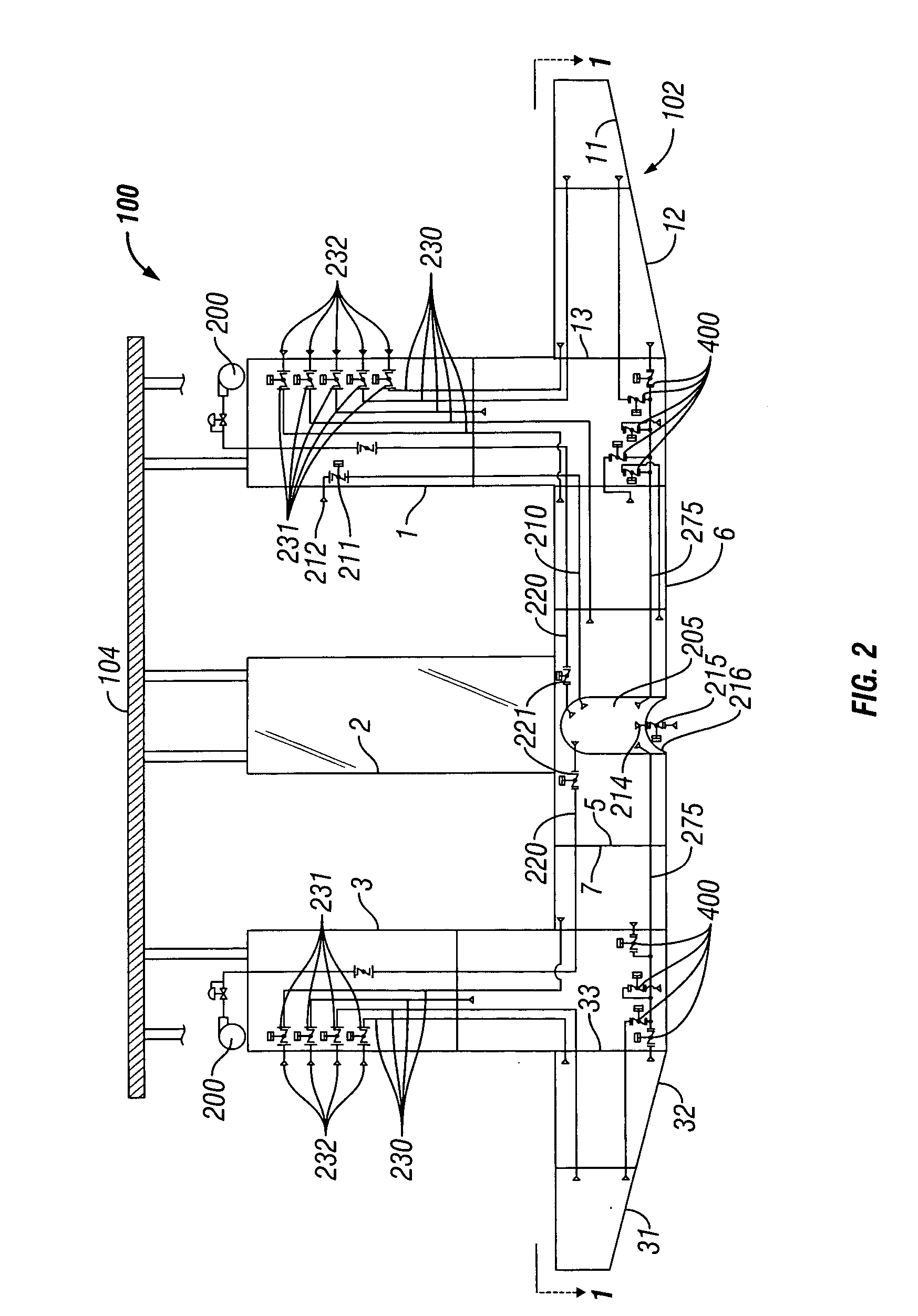
[0023] As shown in FIG. 1, the ballast and de-ballast system according to the invention is preferably employed in a tension leg platform (TLP) 100 having a hull 102 and a number of columns 1, 2, 3, 4 extending upwardly therefrom and supporting a deck 104. The hull 102 has any number of internal ballast tanks but is illustrated with fifteen internal ballast tanks. There are four permanent ballast tanks 11, 21, 31, 41 that are the most outboard tanks in the hull 102. There are eleven tanks within the hull 102 used only temporarily for towing and installation of the TLP to the tendons: Four of these temporary ballast tanks 12, 22, 32, 42 are located immediately inboard of the four permanent ballast tanks 11, 21, 31, 41; four temporary ballast tanks 13, 23, 33, 43 are located at the base of the columns 1, 2, 3, 4, respectively; the three central tanks are the base center tank 5, the wing tank east 6, and the wing tank west 7. However, the ballast / de-ballast system and method may be used...

second embodiment

[0029] As shown in FIG. 5, a second embodiment the ballast and de-ballast system and method according to the invention is preferably employed in a tension leg platform (TLP) 100 having a hull 102 and a number columns 1, 2, 3, 4 extending upwardly therefrom and supporting a deck 104. The hull 102 has any number of internal ballast tanks but is illustrated with sixteen internal ballast tanks. There are four permanent ballast tanks 11, 21, 31, 41 that are the most outboard tanks in the hull 102. There are twelve tanks within the hull 102 used only temporarily for towing and installation of the TLP 100 to the tendons: Four of these temporary ballast tanks 12, 22, 32, 42 are located immediately inboard of the four permanent ballast tanks 11, 21, 31, 41; four temporary ballast tanks 13, 23, 33, 43 are located at the base of the columns 1, 2, 3, 4, respectively; and four tanks are central base tanks 14, 24, 34, 44. However, the ballast / de-ballast system and method may be used with other ve...

third embodiment

[0033]FIG. 7 illustrates the invention. In this system, ballasting and de-ballasting occur through a ballasting manifold system 730 rather than through individual sea chests. The ballasting manifold 730 is preferably located near the keel level. The ballasting manifold 730 is fluidly coupled to the individual ballast tanks 11, 12, 14, 31, 32, 34 with ballast compartment isolation valves 735 connected therebetween for selective isolation. The ballasting manifold 730 is also fluidly coupled to an overboard discharge line 740 with an overboard discharge valve 745 connected therein to allow isolation, and the ballasting manifold 730 is fluidly coupled to a topsides seawater main 750 by seawater isolation valve 755. Each ballast tank is preferably individually vented to atmosphere through discharge openings 701, vent isolation valves 715, and vent piping 716. A compressed gas header 702 ties into tank vents with gas isolation valves 720. A source of compressed gas 200, preferably a high ...


PUM


Abstract

An apparatus and method for ballasting and de-ballasting a vessel having a hull with several watertight ballast compartments. In a first embodiment, a pressure tank is isolatably and fluidly coupled to a common sea chest, to the atmosphere, to ballast compartments via a distribution manifold, and to a source of compressed gas. The pressure tank is first vented and filled with water from the sea chest, then isolated. The filled tank is then coupled to a ballast tank and the source of compressed gas, which displaces water from the tank to the ballast compartment. In other embodiments, ballasting is by venting and flooding compartments using individual sea chests located within the ballast compartments or a firewater system. For de-ballasting, compressed gas displaces ballast water through overboard discharges, through the common sea chest via the pressure tank, or through individual sea chests located within the ballast compartments.

Description

CROSS REFERENCE TO RELATED APPLICATION [0001] This application is based upon provisional application 60 / 539,067 filed on Jan. 22, 2004 and provisional application 60 / 547,952 filed on Feb. 24, 2004, the priorities of which are claimed.BACKGROUND OF THE INVENTION [0002] 1. Field of the Invention [0003] This invention relates generally to tension leg platforms used in the offshore oil and gas production industry and specifically to a method and system for ballasting and de-ballasting a tension leg platform for towing, installation (lock-off to tendons) and use during in-service operation of the platform. [0004] 2. Description of the Prior Art [0005] Tension leg platforms (TLP) are generally used offshore in deep water for the production of hydrocarbons. A typical TLP has a horizontal pontoon hull structure and vertical columns supporting a platform. The hull structure provides buoyancy to the columns and platform. The TLP is anchored by tendons to pilings in the ocean floor, and it is ...

Claims


Application Information

Patent Timeline
Patent Type & Authority Applications(United States)
IPC IPC(8): B63B13/00B63B21/50B63G8/22
CPCB63B13/00B63G8/22B63B2021/505B63B21/502B63B43/06B63B21/50
Inventor KRYSKA, TERRENCECHAPLIN, DAVID E.
Owner SEA ENG ASSOCS
Why Eureka
Try Eureka